


© Analog Devices Inc.
Application Notes |
Why Is my processor leaking power? That sounds like an open-ended question
Question: Why is my processor consuming more power than its data sheet suggests?
Answer:
In my previous article, I talked about the time a device consuming too little power—yes, there is such a thing—got me into trouble. But that’s a rare occurrence. The more common situation I deal with is customers complaining about parts consuming more power than their data sheet claims.
I can recall an instance when a customer walked into my office with his processor board that he said was consuming too much power and draining the battery—and since we proudly claimed that processor to be an ultra low power one, the onus was on us to prove it. As I prepared for the usual grind, cutting off power to different devices on the board one by one until we found the real offender, I remembered a similar case in the not-so-distant past where I had found the culprit to be an LED hanging all by itself between the supply rail and ground without a current limiting resistor for company. I can’t say for sure if it was overcurrent or sheer boredom that killed the LED eventually, but I digress.
Smart from that experience, the first thing I did was to look for an LED burning bright somewhere on the board. However, this time there was no such ray of hope. Also, it turned out that the processor was the only device on the board and, hence, there was no other device for me to try and pin the blame on. My heart sank further when the customer slipped in another piece of information: he had found the power consumption and hence the battery life to be at expected levels when he had tested it in the lab, but the batteries were draining off quickly when the system was deployed in the field. These are the kind of problems that are the toughest to debug, as they are so difficult to reproduce in the first place. This added an analog kind of unpredictability and challenge to a digital world problem, which would generally reside in the predictable and comfortable world of 1s and 0s.
At the simplest level, there are two main domains in which a processor consumes power: core and I/O. When it comes to keeping the core power in check, I would look at things such as the PLL configuration/clock speed, the core supply rail, and the amount of computation activity the core is busy with. There are ways to minimize the core power consumption—for example, reducing the core clock speed or executing certain instructions that force the core to halt or to go into sleep/hibernation. If it’s the I/Os that I suspect to be hogging all the power, I would pay attention to the I/O supply, the frequency at which the I/Os are switching, and the loads they are driving.
These were the only two avenues I could explore. It turned out that there was nothing on the core side of things I could really suspect. It had to be something to do with the I/Os. At this point, the customer revealed that he was using the processor purely for the computational functions and that there was very minimal I/O activity. In fact, he was not using most of the available I/O interfaces on the device.
“Wait! You are not using some of the I/Os. You mean those I/O pins are unused. How have you connected them?”
“I have not connected them anywhere, of course!”
“Aha!”
That was my Eureka moment. Though I didn’t run down the streets screaming, I did take a moment to let it sink in before I sat down to explain.
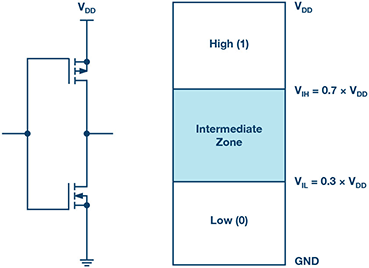 Figure 1. Typical CMOS input circuit (left) and CMOS level logics (right).
A typical CMOS digital input looks like this:
When this input is driven at the recommended high (1) or low (0) levels, the PMOS and NMOS FETs are turned on one at a time, but never together.
There’s a zone of uncertainty in the input drive voltage called the threshold region, where both the PMOS and NMOS can turn on partially at the same time, creating a leakage path between the supply rail and ground.
This is likely to happen when the input is left floating and picks up stray noise. This explains both the high power consumption on the customer’s board and also why it happened randomly.
Figure 1. Typical CMOS input circuit (left) and CMOS level logics (right).
A typical CMOS digital input looks like this:
When this input is driven at the recommended high (1) or low (0) levels, the PMOS and NMOS FETs are turned on one at a time, but never together.
There’s a zone of uncertainty in the input drive voltage called the threshold region, where both the PMOS and NMOS can turn on partially at the same time, creating a leakage path between the supply rail and ground.
This is likely to happen when the input is left floating and picks up stray noise. This explains both the high power consumption on the customer’s board and also why it happened randomly.
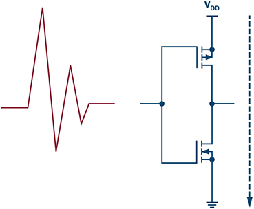 Figure 2. Both PMOS and NMOS turned on partially, creating a leakage path between supply and ground.
In some cases, this could lead to a latch-up like condition where the device continues to draw excessive current and burns out. One could say that’s an easier problem to identify and debug, because there’s a smoking gun in front of you. The kind of problem my customer reported was more difficult to deal with, as it doesn’t raise a big red flag when you are testing in the cool confines of the lab, but causes a lot of grief when it’s out in the field.
Now that we know the root cause of the problem, the obvious solution to this is to drive all the unused inputs to a valid logic level (high or low). However, there’s something in the fine print you need to watch out for. Let’s look at a few more scenarios where improperly handled CMOS inputs can land you into trouble. We need to broaden the scope to include not only the inputs that are totally open/floating, but also the ones that are seemingly connected to a proper logic level.
If you choose to simply tie the pin to a supply rail or ground through a resistor, pay attention to the size of the pull-up or pull-down resistor you use. That, in conjunction with the source/sink current of the pin, could shift the actual voltage level seen by the pin to an undesirable level. In other words, you need to ensure that the pull-up or pull-down is strong enough.
If you choose to drive the pin actively, you should always ensure that the drive strength is good enough for the CMOS load at hand. If not, the noise around the circuit can be strong enough to override the driving signal and force the pin into an unwanted state.
Figure 2. Both PMOS and NMOS turned on partially, creating a leakage path between supply and ground.
In some cases, this could lead to a latch-up like condition where the device continues to draw excessive current and burns out. One could say that’s an easier problem to identify and debug, because there’s a smoking gun in front of you. The kind of problem my customer reported was more difficult to deal with, as it doesn’t raise a big red flag when you are testing in the cool confines of the lab, but causes a lot of grief when it’s out in the field.
Now that we know the root cause of the problem, the obvious solution to this is to drive all the unused inputs to a valid logic level (high or low). However, there’s something in the fine print you need to watch out for. Let’s look at a few more scenarios where improperly handled CMOS inputs can land you into trouble. We need to broaden the scope to include not only the inputs that are totally open/floating, but also the ones that are seemingly connected to a proper logic level.
If you choose to simply tie the pin to a supply rail or ground through a resistor, pay attention to the size of the pull-up or pull-down resistor you use. That, in conjunction with the source/sink current of the pin, could shift the actual voltage level seen by the pin to an undesirable level. In other words, you need to ensure that the pull-up or pull-down is strong enough.
If you choose to drive the pin actively, you should always ensure that the drive strength is good enough for the CMOS load at hand. If not, the noise around the circuit can be strong enough to override the driving signal and force the pin into an unwanted state.
 Let’s examine a couple of scenarios:
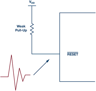
1. A processor working fine in the lab could start rebooting for no apparent reason in the field, because noise got coupled into the line that didn’t have a strong enough pull-up.
Figure 3. Noise coupled into the pin with a weak pull-up can cause the processor to reboot.
2. You can imagine the situation if the CMOS input belongs to a gate driver controlling a high power MOSFET/IGBT, which could inadvertently turn ON when it is not supposed to! Grim tidings indeed.
Figure 4. Noise overriding a weakly driven CMOS input gate driver causing a short circuit on the high voltage bus.
Let’s examine a couple of scenarios:
1. A processor working fine in the lab could start rebooting for no apparent reason in the field, because noise got coupled into the line that didn’t have a strong enough pull-up.
Figure 3. Noise coupled into the pin with a weak pull-up can cause the processor to reboot.
2. You can imagine the situation if the CMOS input belongs to a gate driver controlling a high power MOSFET/IGBT, which could inadvertently turn ON when it is not supposed to! Grim tidings indeed.
Figure 4. Noise overriding a weakly driven CMOS input gate driver causing a short circuit on the high voltage bus.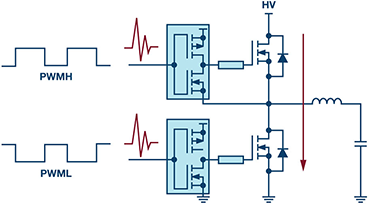 Another related, but not so obvious, problematic scenario is when the driving signals have very slow rise/fall times. In this case, the input can dwell on an intermediate voltage level for a finite amount of time, which may cause all kinds of trouble.
Figure 5. Slow rise and fall times on CMOS inputs creating a momentary short circuit in the transition period.
Another related, but not so obvious, problematic scenario is when the driving signals have very slow rise/fall times. In this case, the input can dwell on an intermediate voltage level for a finite amount of time, which may cause all kinds of trouble.
Figure 5. Slow rise and fall times on CMOS inputs creating a momentary short circuit in the transition period.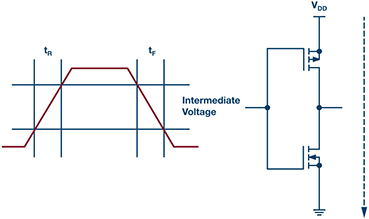 Now that we have looked at some of the potential problems that are applicable to CMOS inputs in general, it would be worthwhile to note that a few devices are better than others at handling these problems by design. For example, parts with Schmitt trigger inputs are inherently better at handling signals that are noisy or have slow edges.
Some of our latest generation processors also take notice of this and have special precautions in the design or explicit guidelines in place to ensure things work smoothly. For example, the ADSP-SC58x/ADSP-2158x data sheet clearly highlights the pins that have internal termination or other logic circuit to ensure the pin is never floating.
In the end, as they always say, it’s a good idea to tie up all the loose ends, especially CMOS digital inputs.
Now that we have looked at some of the potential problems that are applicable to CMOS inputs in general, it would be worthwhile to note that a few devices are better than others at handling these problems by design. For example, parts with Schmitt trigger inputs are inherently better at handling signals that are noisy or have slow edges.
Some of our latest generation processors also take notice of this and have special precautions in the design or explicit guidelines in place to ensure things work smoothly. For example, the ADSP-SC58x/ADSP-2158x data sheet clearly highlights the pins that have internal termination or other logic circuit to ensure the pin is never floating.
In the end, as they always say, it’s a good idea to tie up all the loose ends, especially CMOS digital inputs.
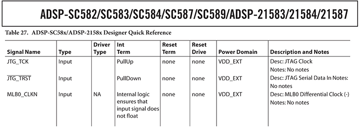 Figure 6. ADSP-SC58x/ADSP-2158x data sheet quick reference.
References:
- ADSP-SC58X/ADSP-2158X: SHARC+ Dual Core DSP with ARM Cortex-A5 data sheet. Analog Devices, Inc., 2017.
- Patil, Abhinay. “Burned by Low Power? When Lower Current Consumption Can Get You Into Trouble.” Analog Dialogue, Vol. 51, 2017.
Figure 6. ADSP-SC58x/ADSP-2158x data sheet quick reference.
References:
- ADSP-SC58X/ADSP-2158X: SHARC+ Dual Core DSP with ARM Cortex-A5 data sheet. Analog Devices, Inc., 2017.
- Patil, Abhinay. “Burned by Low Power? When Lower Current Consumption Can Get You Into Trouble.” Analog Dialogue, Vol. 51, 2017.
Abhinay Patil [abhinay.patil@analog.com] joined © Analog Devices India in 2003 and is currently working as a staff field applications engineer, based in Bangalore. He holds a bachelor of engineering degree in electronics and communications.
Figure 1. Typical CMOS input circuit (left) and CMOS level logics (right).
A typical CMOS digital input looks like this:
When this input is driven at the recommended high (1) or low (0) levels, the PMOS and NMOS FETs are turned on one at a time, but never together.
There’s a zone of uncertainty in the input drive voltage called the threshold region, where both the PMOS and NMOS can turn on partially at the same time, creating a leakage path between the supply rail and ground.
This is likely to happen when the input is left floating and picks up stray noise. This explains both the high power consumption on the customer’s board and also why it happened randomly.
Figure 2. Both PMOS and NMOS turned on partially, creating a leakage path between supply and ground.
In some cases, this could lead to a latch-up like condition where the device continues to draw excessive current and burns out. One could say that’s an easier problem to identify and debug, because there’s a smoking gun in front of you. The kind of problem my customer reported was more difficult to deal with, as it doesn’t raise a big red flag when you are testing in the cool confines of the lab, but causes a lot of grief when it’s out in the field.
Now that we know the root cause of the problem, the obvious solution to this is to drive all the unused inputs to a valid logic level (high or low). However, there’s something in the fine print you need to watch out for. Let’s look at a few more scenarios where improperly handled CMOS inputs can land you into trouble. We need to broaden the scope to include not only the inputs that are totally open/floating, but also the ones that are seemingly connected to a proper logic level.
If you choose to simply tie the pin to a supply rail or ground through a resistor, pay attention to the size of the pull-up or pull-down resistor you use. That, in conjunction with the source/sink current of the pin, could shift the actual voltage level seen by the pin to an undesirable level. In other words, you need to ensure that the pull-up or pull-down is strong enough.
If you choose to drive the pin actively, you should always ensure that the drive strength is good enough for the CMOS load at hand. If not, the noise around the circuit can be strong enough to override the driving signal and force the pin into an unwanted state.
Let’s examine a couple of scenarios:
1. A processor working fine in the lab could start rebooting for no apparent reason in the field, because noise got coupled into the line that didn’t have a strong enough pull-up.
Figure 3. Noise coupled into the pin with a weak pull-up can cause the processor to reboot.
2. You can imagine the situation if the CMOS input belongs to a gate driver controlling a high power MOSFET/IGBT, which could inadvertently turn ON when it is not supposed to! Grim tidings indeed.
Figure 4. Noise overriding a weakly driven CMOS input gate driver causing a short circuit on the high voltage bus.
Another related, but not so obvious, problematic scenario is when the driving signals have very slow rise/fall times. In this case, the input can dwell on an intermediate voltage level for a finite amount of time, which may cause all kinds of trouble.
Figure 5. Slow rise and fall times on CMOS inputs creating a momentary short circuit in the transition period.
Now that we have looked at some of the potential problems that are applicable to CMOS inputs in general, it would be worthwhile to note that a few devices are better than others at handling these problems by design. For example, parts with Schmitt trigger inputs are inherently better at handling signals that are noisy or have slow edges.
Some of our latest generation processors also take notice of this and have special precautions in the design or explicit guidelines in place to ensure things work smoothly. For example, the ADSP-SC58x/ADSP-2158x data sheet clearly highlights the pins that have internal termination or other logic circuit to ensure the pin is never floating.
In the end, as they always say, it’s a good idea to tie up all the loose ends, especially CMOS digital inputs.
Figure 6. ADSP-SC58x/ADSP-2158x data sheet quick reference.
References:
- ADSP-SC58X/ADSP-2158X: SHARC+ Dual Core DSP with ARM Cortex-A5 data sheet. Analog Devices, Inc., 2017.
- Patil, Abhinay. “Burned by Low Power? When Lower Current Consumption Can Get You Into Trouble.” Analog Dialogue, Vol. 51, 2017.Abhinay Patil [abhinay.patil@analog.com] joined © Analog Devices India in 2003 and is currently working as a staff field applications engineer, based in Bangalore. He holds a bachelor of engineering degree in electronics and communications.