


© Analog Devices Inc.
Application Notes |
Home on the range: Getting multiple gain ranges with instrumentation amplifiers
Question: I have an instrumentation amplifier, but I need wider dynamic range than I can get with a single gain. Can I multiplex gain resistors to get programmable gain?
Answer: In order to maximize dynamic range in precision sensor measurements, it may be necessary to use a programmable gain instrumentation amplifier (PGIA). Because most instrumentation amplifiers (in-amps) use an external gain resistor (RG) to set the gain, it would seem the desired programmed gains can be achieved with a set of multiplexed gain resistors. While this is possible, there are three major issues to consider before implementing a system this way with a solid-state multiplexer: supply and signal voltage limitations, switch capacitance, and on resistance.
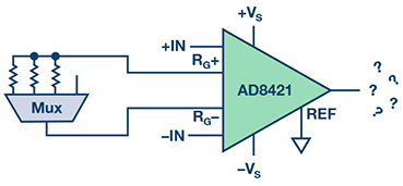 Figure 1. AD8421 PGIA with multiplexer.
Staying Within the Signal Range
Solid-state CMOS switches require a power supply. When the source or drain voltage exceeds the supply, fault current can flow and cause an incorrect output. The voltage at each RG pin is typically within a diode drop of the voltage at the corresponding input; therefore, the signal voltage range of the switch must be greater than the input range of the in-amp.
Considering the Capacitance
The switch capacitance is similar to hanging a capacitor on one of the RG pins and leaving the other RG pin alone. A large enough capacitor could cause peaking or instability, but the more overlooked issue is the effect on the common-mode rejection ratio. In board layout, ground plane is generally removed from beneath the RG pins, because capacitive imbalance less than 1 pF greatly reduces the ac CMRR. The switch capacitance can be in the tens of picofarads, causing large errors. Taking the simple case with an in-amp with perfect CMRR, no RG present, and capacitance at only one RG pin, the CMRR due to the capacitance can be approximated by:
Figure 1. AD8421 PGIA with multiplexer.
Staying Within the Signal Range
Solid-state CMOS switches require a power supply. When the source or drain voltage exceeds the supply, fault current can flow and cause an incorrect output. The voltage at each RG pin is typically within a diode drop of the voltage at the corresponding input; therefore, the signal voltage range of the switch must be greater than the input range of the in-amp.
Considering the Capacitance
The switch capacitance is similar to hanging a capacitor on one of the RG pins and leaving the other RG pin alone. A large enough capacitor could cause peaking or instability, but the more overlooked issue is the effect on the common-mode rejection ratio. In board layout, ground plane is generally removed from beneath the RG pins, because capacitive imbalance less than 1 pF greatly reduces the ac CMRR. The switch capacitance can be in the tens of picofarads, causing large errors. Taking the simple case with an in-amp with perfect CMRR, no RG present, and capacitance at only one RG pin, the CMRR due to the capacitance can be approximated by:
 For example, if the internal feedback resistance, RF = 25 kΩ, and CRG = 10 pF, the CMRR at 10 kHz is only 36 dB. This suggests using a low capacitance switch or a balanced switching architecture like the one shown in Figure 2 with SPST switches.
Regarding the Resistance
Finally, the on resistance of the switch impacts the gain directly according to the gain equation of the in-amp. If the on resistance is low enough that the desired gain is still achievable, this might be okay. However, the on resistance of the switch changes with the drain voltage, specified as RFLAT(ON). The change in the switch resistance creates both a gain dependence on the common-mode voltage and a gain nonlinearity effect. For example, using an RG of 1 kΩ and a switch with 10 Ω RFLAT(ON), there will be a 1% gain uncertainty over the common-mode range. A certain portion of that will translate to the differential signal (for example, a 2 Ω change would be 2000 ppm nonlinearity). This suggests using a low on resistance switch, which is contrary to the suggestion of a low capacitance switch because low on resistance is achieved with large transistor device size whereas low capacitance is achieved with small transistors. The ADG5412F fault-protected, quad SPST switch provides a good solution in many cases. The architecture of these fault-protected switches allows them to provide 10 Ω on resistance that is very flat across the signal range and only 12 pF off capacitance.
For example, if the internal feedback resistance, RF = 25 kΩ, and CRG = 10 pF, the CMRR at 10 kHz is only 36 dB. This suggests using a low capacitance switch or a balanced switching architecture like the one shown in Figure 2 with SPST switches.
Regarding the Resistance
Finally, the on resistance of the switch impacts the gain directly according to the gain equation of the in-amp. If the on resistance is low enough that the desired gain is still achievable, this might be okay. However, the on resistance of the switch changes with the drain voltage, specified as RFLAT(ON). The change in the switch resistance creates both a gain dependence on the common-mode voltage and a gain nonlinearity effect. For example, using an RG of 1 kΩ and a switch with 10 Ω RFLAT(ON), there will be a 1% gain uncertainty over the common-mode range. A certain portion of that will translate to the differential signal (for example, a 2 Ω change would be 2000 ppm nonlinearity). This suggests using a low on resistance switch, which is contrary to the suggestion of a low capacitance switch because low on resistance is achieved with large transistor device size whereas low capacitance is achieved with small transistors. The ADG5412F fault-protected, quad SPST switch provides a good solution in many cases. The architecture of these fault-protected switches allows them to provide 10 Ω on resistance that is very flat across the signal range and only 12 pF off capacitance.
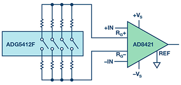 Figure 2. Balanced PGIA with ADG5412F quad SPST and AD8421.
Acknowledging the Alternatives
There are also other ways to implement the programmable gain in-amp function if these circuits don’t meet the design requirements. It is highly recommended to choose an integrated PGIA if there is one that is appropriate. Integrated PGIAs are designed for high performance, have a smaller footprint, and fewer parasitics than discrete solutions, and the specifications include the effects from the internal switches. Some good examples of integrated PGIAs are AD8231, AD8250/AD8251/AD8253, and LTC6915. Additionally, there are solutions with higher levels of integration that include this function, such as AD7124-8 and ADAS3022.
Conclusion
In-amps are high precision components that are made as balanced as possible at the silicon level in order to reject common-mode. It is possible to build a programmable gain in-amp using solid-state switches, but it is also very easy to throw off the balance that defines the in-amp and reduce the precision of the circuit. The nonideal effects of the switches need to be considered in order to make the necessary trade-offs. Balanced switching architectures and modern switches like ADG5412F are great tools to optimize these designs. Integrated PGIAs are recommended because the effects of the switches are already included in the specifications.
Figure 2. Balanced PGIA with ADG5412F quad SPST and AD8421.
Acknowledging the Alternatives
There are also other ways to implement the programmable gain in-amp function if these circuits don’t meet the design requirements. It is highly recommended to choose an integrated PGIA if there is one that is appropriate. Integrated PGIAs are designed for high performance, have a smaller footprint, and fewer parasitics than discrete solutions, and the specifications include the effects from the internal switches. Some good examples of integrated PGIAs are AD8231, AD8250/AD8251/AD8253, and LTC6915. Additionally, there are solutions with higher levels of integration that include this function, such as AD7124-8 and ADAS3022.
Conclusion
In-amps are high precision components that are made as balanced as possible at the silicon level in order to reject common-mode. It is possible to build a programmable gain in-amp using solid-state switches, but it is also very easy to throw off the balance that defines the in-amp and reduce the precision of the circuit. The nonideal effects of the switches need to be considered in order to make the necessary trade-offs. Balanced switching architectures and modern switches like ADG5412F are great tools to optimize these designs. Integrated PGIAs are recommended because the effects of the switches are already included in the specifications.
Author: Scott Hunt [scott.hunt@analog.com] is a system applications engineer specializing in precision instrumentation in the Linear and Precision Technology Group of © Analog Devices, Inc., in Wilmington, MA. Scott joined Analog Devices in 2011 as a product applications engineer for high performance integrated precision amplifiers such as instrumentation amplifiers. He has a bachelor’s degree in electrical and computer systems engineering from Rensselaer Polytechnic Institute.
Figure 1. AD8421 PGIA with multiplexer.
Staying Within the Signal Range
Solid-state CMOS switches require a power supply. When the source or drain voltage exceeds the supply, fault current can flow and cause an incorrect output. The voltage at each RG pin is typically within a diode drop of the voltage at the corresponding input; therefore, the signal voltage range of the switch must be greater than the input range of the in-amp.
Considering the Capacitance
The switch capacitance is similar to hanging a capacitor on one of the RG pins and leaving the other RG pin alone. A large enough capacitor could cause peaking or instability, but the more overlooked issue is the effect on the common-mode rejection ratio. In board layout, ground plane is generally removed from beneath the RG pins, because capacitive imbalance less than 1 pF greatly reduces the ac CMRR. The switch capacitance can be in the tens of picofarads, causing large errors. Taking the simple case with an in-amp with perfect CMRR, no RG present, and capacitance at only one RG pin, the CMRR due to the capacitance can be approximated by:
For example, if the internal feedback resistance, RF = 25 kΩ, and CRG = 10 pF, the CMRR at 10 kHz is only 36 dB. This suggests using a low capacitance switch or a balanced switching architecture like the one shown in Figure 2 with SPST switches.
Regarding the Resistance
Finally, the on resistance of the switch impacts the gain directly according to the gain equation of the in-amp. If the on resistance is low enough that the desired gain is still achievable, this might be okay. However, the on resistance of the switch changes with the drain voltage, specified as RFLAT(ON). The change in the switch resistance creates both a gain dependence on the common-mode voltage and a gain nonlinearity effect. For example, using an RG of 1 kΩ and a switch with 10 Ω RFLAT(ON), there will be a 1% gain uncertainty over the common-mode range. A certain portion of that will translate to the differential signal (for example, a 2 Ω change would be 2000 ppm nonlinearity). This suggests using a low on resistance switch, which is contrary to the suggestion of a low capacitance switch because low on resistance is achieved with large transistor device size whereas low capacitance is achieved with small transistors. The ADG5412F fault-protected, quad SPST switch provides a good solution in many cases. The architecture of these fault-protected switches allows them to provide 10 Ω on resistance that is very flat across the signal range and only 12 pF off capacitance.
Figure 2. Balanced PGIA with ADG5412F quad SPST and AD8421.
Acknowledging the Alternatives
There are also other ways to implement the programmable gain in-amp function if these circuits don’t meet the design requirements. It is highly recommended to choose an integrated PGIA if there is one that is appropriate. Integrated PGIAs are designed for high performance, have a smaller footprint, and fewer parasitics than discrete solutions, and the specifications include the effects from the internal switches. Some good examples of integrated PGIAs are AD8231, AD8250/AD8251/AD8253, and LTC6915. Additionally, there are solutions with higher levels of integration that include this function, such as AD7124-8 and ADAS3022.
Conclusion
In-amps are high precision components that are made as balanced as possible at the silicon level in order to reject common-mode. It is possible to build a programmable gain in-amp using solid-state switches, but it is also very easy to throw off the balance that defines the in-amp and reduce the precision of the circuit. The nonideal effects of the switches need to be considered in order to make the necessary trade-offs. Balanced switching architectures and modern switches like ADG5412F are great tools to optimize these designs. Integrated PGIAs are recommended because the effects of the switches are already included in the specifications.Author: Scott Hunt [scott.hunt@analog.com] is a system applications engineer specializing in precision instrumentation in the Linear and Precision Technology Group of © Analog Devices, Inc., in Wilmington, MA. Scott joined Analog Devices in 2011 as a product applications engineer for high performance integrated precision amplifiers such as instrumentation amplifiers. He has a bachelor’s degree in electrical and computer systems engineering from Rensselaer Polytechnic Institute.