

Sponsored content by Mentor Graphics
How do we improve on DFM for PCBs?
How do we make DFM more accessible to more people? How do we streamline the DFM process so that optimized designs get released to manufacturing during the initial design process?
We can do so with these two steps:
1. Make it much simpler to setup and maintain the DFM rules. If the rules setup is simplified, they are easier to maintain as the board technology and suppliers’ process capabilities evolve. As such, DFM results will yield only true DFM issues that need attention and no false calls that consume a significant amount of time to filter through.
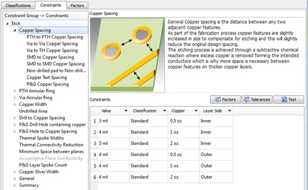
The DFM rules setup needs to be intuitive to anyone familiar with PCBs. The GUI must facilitate simple setup of the factors, classifications, and constraints required. An intelligent DFM system will also know the hierarchical relationship between different DFM categories and allow setting up the minimum, while receiving the maximum benefit.
 2. By putting the logic of the DFM process into the DFM software itself, making it an expert system. Let the DFM software application read the intelligence inherent in the PCB design data to automatically determine the PCB classification and, thus which DFM rules to apply. The layer count, board thickness, via hole sizes and construction method are all attributes or properties within the CAD data. Leverage that intelligence.
Multiple factors affect the DFM rules to be used. For example, a common factor is the copper weight of the layer. The PCB fabricators will add an etch compensation value to each layer, and the amount of compensation will depend on whether it is 0.5, 1, or 2 oz. copper. Thus, when DFM analysis is performed for etch, a different spacing value and line width is used based on copper weight for that layer.
Another example is the construction of the PCB. If it is conventionally laminated in a single step, the manufacturing process tolerances will be different from PCBs constructed using sequential lamination or buildup technology. Accordingly, the DFM rules will vary by construction type.
As a final example, the aspect ratio of the PCB also affects the manufacturing process tolerances. The PCB fabricators will stack multiple panels on their drill machines, if possible, to save money. However, if the PCB aspect ratio is too high, they will need to drill the panels separately, which will end up making the cost of the boards higher. Designers need to know the acceptable aspect ratios their fabricators can comfortably accommodate.
2. By putting the logic of the DFM process into the DFM software itself, making it an expert system. Let the DFM software application read the intelligence inherent in the PCB design data to automatically determine the PCB classification and, thus which DFM rules to apply. The layer count, board thickness, via hole sizes and construction method are all attributes or properties within the CAD data. Leverage that intelligence.
Multiple factors affect the DFM rules to be used. For example, a common factor is the copper weight of the layer. The PCB fabricators will add an etch compensation value to each layer, and the amount of compensation will depend on whether it is 0.5, 1, or 2 oz. copper. Thus, when DFM analysis is performed for etch, a different spacing value and line width is used based on copper weight for that layer.
Another example is the construction of the PCB. If it is conventionally laminated in a single step, the manufacturing process tolerances will be different from PCBs constructed using sequential lamination or buildup technology. Accordingly, the DFM rules will vary by construction type.
As a final example, the aspect ratio of the PCB also affects the manufacturing process tolerances. The PCB fabricators will stack multiple panels on their drill machines, if possible, to save money. However, if the PCB aspect ratio is too high, they will need to drill the panels separately, which will end up making the cost of the boards higher. Designers need to know the acceptable aspect ratios their fabricators can comfortably accommodate.
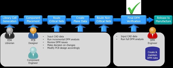 A smart system is one that incorporates the knowledge of a subject matter expert into the application software. More people then can profit from the expertise–the knowledge becomes scalable. Because we often equate expertise to efficiencies and quality, it behooves the electronics industry to employ expert systems whenever possible. DFM for PCBs needs an expert
2. By putting the logic of the DFM process into the DFM software itself, making it an expert system. Let the DFM software application read the intelligence inherent in the PCB design data to automatically determine the PCB classification and, thus which DFM rules to apply. The layer count, board thickness, via hole sizes and construction method are all attributes or properties within the CAD data. Leverage that intelligence.
Multiple factors affect the DFM rules to be used. For example, a common factor is the copper weight of the layer. The PCB fabricators will add an etch compensation value to each layer, and the amount of compensation will depend on whether it is 0.5, 1, or 2 oz. copper. Thus, when DFM analysis is performed for etch, a different spacing value and line width is used based on copper weight for that layer.
Another example is the construction of the PCB. If it is conventionally laminated in a single step, the manufacturing process tolerances will be different from PCBs constructed using sequential lamination or buildup technology. Accordingly, the DFM rules will vary by construction type.
As a final example, the aspect ratio of the PCB also affects the manufacturing process tolerances. The PCB fabricators will stack multiple panels on their drill machines, if possible, to save money. However, if the PCB aspect ratio is too high, they will need to drill the panels separately, which will end up making the cost of the boards higher. Designers need to know the acceptable aspect ratios their fabricators can comfortably accommodate.
A smart system is one that incorporates the knowledge of a subject matter expert into the application software. More people then can profit from the expertise–the knowledge becomes scalable. Because we often equate expertise to efficiencies and quality, it behooves the electronics industry to employ expert systems whenever possible. DFM for PCBs needs an expert