

Three options to optimize the control loop of power converters
Question: Is there an easy way to select the external components for power converters?
Answer: There are three possibilities.
Almost every power supply has a control loop to maintain the output voltage at a constant value. In the design of a power supply, the aim is to optimize the control loop so that if there are fluctuations in the input voltage or load transients, the deviations in the controlled output voltage from the setpoint are minimized. An important relationship here is the size of the output capacitors in relation to the response speed of the switching regulator IC. If the response of the loop is particularly fast, smaller output capacitors can be used while keeping the output voltage within the permissible range. Thus, optimization of the response speed of the switching regulator leads to reduced system cost and a lower space requirement for the circuit because smaller output capacitors can be used.
With most switching regulator ICs, there is a compensation pin, frequently called ITH or VC, for control loop adjustment. With skillful selection of capacitances and resistances, poles and zeros can be added to the transfer function of the control loop to ensure optimal dynamic performance and high control loop stability. But how are these compensation components selected?
There are three approaches that can be taken for this.
- 1. Manual calculation with data taken from the data sheet:
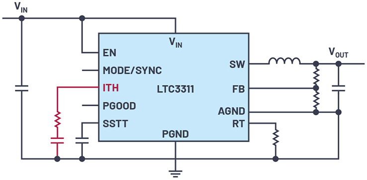
The first method uses the calculation formulas in the data sheet for a switching regulator IC. A stabilization concept is proposed in consideration of one selected power stage. Figure 1 shows an LTC3311 IC with the corresponding ITH pin and suitable compensation components.
- 2. Using a design tool:
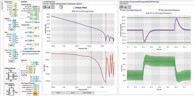
The second way to find a suitable transfer function setting involves using a design tool such as LTpowerCAD® to calculate the external components. This approach provides additional insight into the control loop response. Figure 2 shows the LTpowerCAD user interface with a graphical representation of the control loop in a Bode plot, as well as the response of the output voltage to load transients in the time domain. The ITH setting values can be comfortably varied and an optimal setting can be found with this method.
There’s a saying from Goethe that “all theory is gray.” In practice, there are parasitic components that should be accounted for and checked before development transitions to mass production. The compensation components that have already been selected are connected to the ITH pin and load transient tests are performed to check whether the voltage change at VOUT is within the permissible range and whether the voltage converter is working stably.
This hardware test only checks one setting option for compensation. However, it is possible that the setting can be optimized with slightly modified values. To find this out, all kinds of soldering work must be done on the hardware because the external components must be changed with new values to find the optimal compensation component combination.
- 3. The elegant approach—using a preconfigured RC network:
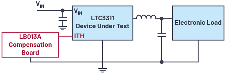
Figure 3 shows a third, elegant way to solve this problem using a preconfigured RC network. The LB013A board from Analog Devices is a small circuit board on which a simple switchable and adjustable RC network is implemented. The total capacitance and resistance values can be changed through actuation of small switches and rotation of potentiometers. The laborious soldering of compensation modules is done away with and the compensation setting can be optimized in real time during a load transient test. A circuit board such as the LB013A is easy to make, but it can also be purchased from Analog Devices.
With these three methods for optimizing the compensation of a switching regulator, compensation of any power supply is possible.
About the Author: Frederik Dostal studied microelectronics at the University of Erlangen in Germany. Starting work in the power management business in 2001, he has been active in various applications positions including four years in Phoenix, Arizona, where he worked on switch-mode power supplies. He joined © Analog Devices in 2009 and works as a field applications engineer for power management at Analog Devices in München. He can be reached at frederik.dostal@analog.com.
