

© Analog Devices Inc.
Application Notes |
Simple circuit measures relative intensity of two light sources
Question: Can I measure the difference between two light sources with an instrumentation amplifier?
Answer: Yes, by replacing the main setting resistor of an instrumentation amplifier with two photoresistors.
In many lighting applications, measuring the relative intensity of two light sources is more important than measuring their individual intensity. This ensures that two light sources shine with the same intensity. For example, it is helpful to compare the brightness inside a control room (Room 1) to a second room (Room 2) in the same building so the adjustment can be made any time of day as well as night, or, if you have a production system, you might want to ensure that the bright light conditions do not change.
One way to determine the relative intensity is to measure the different outputs of two additional light detectors. Their difference will be converted to a single-ended voltage signal with ground reference.
The circuit in Figure 1 shows a simple but effective way to solve this problem, by using an instrumentation amplifier with resistor gain control, such as the AD623.
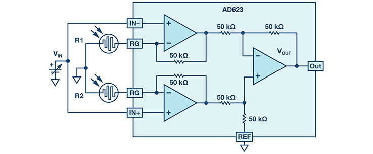 Figure 1. A simple circuit that measures relative light densities.
Note that in this circuit, there are two special resistors, R1 and R2. R1 (LDR1) measures the brightness of the two light sources.
What is an LDR? The term stands for light dependent resistor or photoresistor. It is a passive electronic component with a resistor that has variable resistance depending on light intensity. Light dependent resistors come in different shapes and colors and they are useful in many electronic circuits, especially in alarms, switching devices, clocks, and street lights.
Figure 1. A simple circuit that measures relative light densities.
Note that in this circuit, there are two special resistors, R1 and R2. R1 (LDR1) measures the brightness of the two light sources.
What is an LDR? The term stands for light dependent resistor or photoresistor. It is a passive electronic component with a resistor that has variable resistance depending on light intensity. Light dependent resistors come in different shapes and colors and they are useful in many electronic circuits, especially in alarms, switching devices, clocks, and street lights.
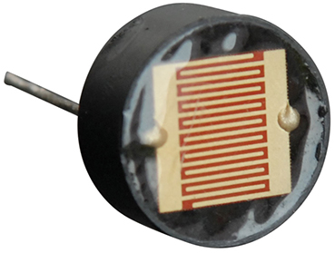 Figure 2. RadioShack part #276-1657.
In general, LDRs’ resistance is very high in darkness—almost high as 1 MΩ—but when light falls on the LDR, the resistance falls to a few kΩ (10 kΩ to 20 kΩ at 10 lux, 2 kΩ to 4 kΩ at 100 lux), depending on the model. The LDR used for this schematic is from RadioShack (part # 276-1657).
The schematic in Figure 1 employs an AD623 and two LDRs. As the main sensor, photoresistor R1 is a reference point light source. It is used as a baseline for light intensity and it is located in the control room. If you are comparing more than two light sources, you should use this light source as a reference during every comparison. This comparison can happen at night or during the day. Keep in mind that it takes 8 msec to 12 msec for a change in resistance to take place. It also take seconds for the resistance to change back to its initial value.
The design is very simple. The power supplies of the system are ±5 V and the input voltage at both inputs is VIN. Therefore, the same voltage is on one end of each photoresistor and ground on their other end. If the same amount of light fell on both photoresistors, the current difference between them would be zero because their resistances are equal. The result is that the output voltage is at zero volts. When the two rooms are not equally illuminated, there is a difference between the intensities of the two light sources and this creates a voltage at the output of the system. The polarity of this voltage indicates which room is brighter. If the output voltage was positive, this would mean that more light has fallen on LDR2 and vice versa.
Figure 2. RadioShack part #276-1657.
In general, LDRs’ resistance is very high in darkness—almost high as 1 MΩ—but when light falls on the LDR, the resistance falls to a few kΩ (10 kΩ to 20 kΩ at 10 lux, 2 kΩ to 4 kΩ at 100 lux), depending on the model. The LDR used for this schematic is from RadioShack (part # 276-1657).
The schematic in Figure 1 employs an AD623 and two LDRs. As the main sensor, photoresistor R1 is a reference point light source. It is used as a baseline for light intensity and it is located in the control room. If you are comparing more than two light sources, you should use this light source as a reference during every comparison. This comparison can happen at night or during the day. Keep in mind that it takes 8 msec to 12 msec for a change in resistance to take place. It also take seconds for the resistance to change back to its initial value.
The design is very simple. The power supplies of the system are ±5 V and the input voltage at both inputs is VIN. Therefore, the same voltage is on one end of each photoresistor and ground on their other end. If the same amount of light fell on both photoresistors, the current difference between them would be zero because their resistances are equal. The result is that the output voltage is at zero volts. When the two rooms are not equally illuminated, there is a difference between the intensities of the two light sources and this creates a voltage at the output of the system. The polarity of this voltage indicates which room is brighter. If the output voltage was positive, this would mean that more light has fallen on LDR2 and vice versa.
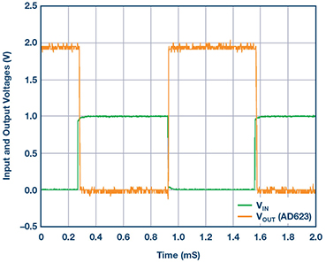 Figure 3. Output voltage indicates the relative light intensity.
Figure 3 shows a scope plot of the output waveform. With the input voltage is 1 V p-p square wave at a frequency of 1 kHz, the output (about 2 V) indicates that the light source in Room 2 is brighter.
In the circuit in this article, there are two LEDs at the output of the AD623. The red LED with the positive side connected to the output would turn on when the output is positive (light source 2 is brighter) and the yellow LED with the positive side to ground would be turned on when light source 1 is brighter. Note that the brightness of the LED shows the amplitude level of the relative intensity of the room.
When both rooms appear equally bright, their illuminance is equal and the output is 0 V while both LEDs are off.
The voltage at the output of the circuit is:
Figure 3. Output voltage indicates the relative light intensity.
Figure 3 shows a scope plot of the output waveform. With the input voltage is 1 V p-p square wave at a frequency of 1 kHz, the output (about 2 V) indicates that the light source in Room 2 is brighter.
In the circuit in this article, there are two LEDs at the output of the AD623. The red LED with the positive side connected to the output would turn on when the output is positive (light source 2 is brighter) and the yellow LED with the positive side to ground would be turned on when light source 1 is brighter. Note that the brightness of the LED shows the amplitude level of the relative intensity of the room.
When both rooms appear equally bright, their illuminance is equal and the output is 0 V while both LEDs are off.
The voltage at the output of the circuit is:
 The rms value of the output is the intensity level of two light sources.
After calibrating the value of LDR1 to find the precise resistance value at a certain brightness, LDR1 can be replaced by a pure resistor and then the system will compare the value of LDR2 to a certain brightness all the time. The fixed resistor then works as a reference for a known light reference. This kind of circuit can be a solar seeker—namely, a simple device that tracks a light source. Such a device can keep solar panels aligned with the Sun, or be used in search and rescue robots that try to guide trapped people toward light. In order to implement the solar seeker, a servo motor that rotates the photoresistors can be used.
Using AD623, one can find out the efficiency of two light bulbs by putting them in the different rooms together with LDR1 and LDR2, respectively. This circuit has low power consumption and can be powered just by two AA batteries, which is useful in power sensitive applications.
The rms value of the output is the intensity level of two light sources.
After calibrating the value of LDR1 to find the precise resistance value at a certain brightness, LDR1 can be replaced by a pure resistor and then the system will compare the value of LDR2 to a certain brightness all the time. The fixed resistor then works as a reference for a known light reference. This kind of circuit can be a solar seeker—namely, a simple device that tracks a light source. Such a device can keep solar panels aligned with the Sun, or be used in search and rescue robots that try to guide trapped people toward light. In order to implement the solar seeker, a servo motor that rotates the photoresistors can be used.
Using AD623, one can find out the efficiency of two light bulbs by putting them in the different rooms together with LDR1 and LDR2, respectively. This circuit has low power consumption and can be powered just by two AA batteries, which is useful in power sensitive applications.
Author: Chau Tran [chau.tran@analog.com] joined © Analog Devices in 1984, where he works in the Instrumentation Amplifier Products (IAP) Group in Wilmington, MA. In 1990, he graduated with an M.S.E.E. degree from Tufts University. Tran holds more than 10 patents and has authored more than 10 technical articles.
Figure 1. A simple circuit that measures relative light densities.
Note that in this circuit, there are two special resistors, R1 and R2. R1 (LDR1) measures the brightness of the two light sources.
What is an LDR? The term stands for light dependent resistor or photoresistor. It is a passive electronic component with a resistor that has variable resistance depending on light intensity. Light dependent resistors come in different shapes and colors and they are useful in many electronic circuits, especially in alarms, switching devices, clocks, and street lights.
Figure 2. RadioShack part #276-1657.
In general, LDRs’ resistance is very high in darkness—almost high as 1 MΩ—but when light falls on the LDR, the resistance falls to a few kΩ (10 kΩ to 20 kΩ at 10 lux, 2 kΩ to 4 kΩ at 100 lux), depending on the model. The LDR used for this schematic is from RadioShack (part # 276-1657).
The schematic in Figure 1 employs an AD623 and two LDRs. As the main sensor, photoresistor R1 is a reference point light source. It is used as a baseline for light intensity and it is located in the control room. If you are comparing more than two light sources, you should use this light source as a reference during every comparison. This comparison can happen at night or during the day. Keep in mind that it takes 8 msec to 12 msec for a change in resistance to take place. It also take seconds for the resistance to change back to its initial value.
The design is very simple. The power supplies of the system are ±5 V and the input voltage at both inputs is VIN. Therefore, the same voltage is on one end of each photoresistor and ground on their other end. If the same amount of light fell on both photoresistors, the current difference between them would be zero because their resistances are equal. The result is that the output voltage is at zero volts. When the two rooms are not equally illuminated, there is a difference between the intensities of the two light sources and this creates a voltage at the output of the system. The polarity of this voltage indicates which room is brighter. If the output voltage was positive, this would mean that more light has fallen on LDR2 and vice versa.
Figure 3. Output voltage indicates the relative light intensity.
Figure 3 shows a scope plot of the output waveform. With the input voltage is 1 V p-p square wave at a frequency of 1 kHz, the output (about 2 V) indicates that the light source in Room 2 is brighter.
In the circuit in this article, there are two LEDs at the output of the AD623. The red LED with the positive side connected to the output would turn on when the output is positive (light source 2 is brighter) and the yellow LED with the positive side to ground would be turned on when light source 1 is brighter. Note that the brightness of the LED shows the amplitude level of the relative intensity of the room.
When both rooms appear equally bright, their illuminance is equal and the output is 0 V while both LEDs are off.
The voltage at the output of the circuit is:
The rms value of the output is the intensity level of two light sources.
After calibrating the value of LDR1 to find the precise resistance value at a certain brightness, LDR1 can be replaced by a pure resistor and then the system will compare the value of LDR2 to a certain brightness all the time. The fixed resistor then works as a reference for a known light reference. This kind of circuit can be a solar seeker—namely, a simple device that tracks a light source. Such a device can keep solar panels aligned with the Sun, or be used in search and rescue robots that try to guide trapped people toward light. In order to implement the solar seeker, a servo motor that rotates the photoresistors can be used.
Using AD623, one can find out the efficiency of two light bulbs by putting them in the different rooms together with LDR1 and LDR2, respectively. This circuit has low power consumption and can be powered just by two AA batteries, which is useful in power sensitive applications.Author: Chau Tran [chau.tran@analog.com] joined © Analog Devices in 1984, where he works in the Instrumentation Amplifier Products (IAP) Group in Wilmington, MA. In 1990, he graduated with an M.S.E.E. degree from Tufts University. Tran holds more than 10 patents and has authored more than 10 technical articles.