


© Analog Devices Inc.
Application Notes |
Synchronous Rectification on the Secondary Side
Question: How can I increase the efficiency of my isolated power supply?
Answer: For most step-down regulators, also called buck regulators, it is standard in typical applications to use active switches instead of Schottky diodes. This can greatly increase conversion efficiency, especially when low output voltages are generated. And in applications where galvanic isolation is needed, synchronous rectification can be used to increase conversion efficiency as well. Figure 1 shows a forward converter with synchronous rectification on the secondary side.
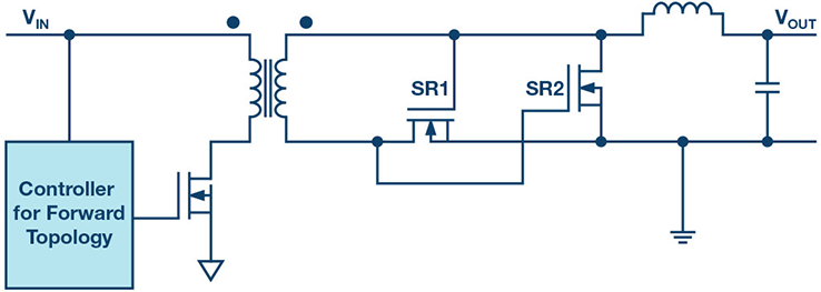 Figure 1. Self-driven synchronous rectification of a forward converter.
Driving the switches for the synchronous rectification can be done in different ways. One simple concept for doing so involves driving across the transformer’s secondary winding. This is shown in Figure 1. In this example, the input voltage range may not be very wide. With the minimum input voltage, there needs to be enough voltage at the gates of SR1 and SR2 so that the switches can be reliably turned on. To ensure that the gate voltage at MOSFET SR1 and MOSFET SR2 does not exceed their maximum rated voltage, the maximum input voltage cannot be too high.
In all power supplies with synchronous rectification, a negative current may develop through the circuit. For example, if the capacitors at the output of the circuit are precharged before the circuit is turned on, current could flow from the output side to the input side. The negative current could increase the voltages at MOSFET SR1 and MOSFET SR2 in such a way that they might be damaged. Care must be taken to protect the switches in such an event.
Figure 1. Self-driven synchronous rectification of a forward converter.
Driving the switches for the synchronous rectification can be done in different ways. One simple concept for doing so involves driving across the transformer’s secondary winding. This is shown in Figure 1. In this example, the input voltage range may not be very wide. With the minimum input voltage, there needs to be enough voltage at the gates of SR1 and SR2 so that the switches can be reliably turned on. To ensure that the gate voltage at MOSFET SR1 and MOSFET SR2 does not exceed their maximum rated voltage, the maximum input voltage cannot be too high.
In all power supplies with synchronous rectification, a negative current may develop through the circuit. For example, if the capacitors at the output of the circuit are precharged before the circuit is turned on, current could flow from the output side to the input side. The negative current could increase the voltages at MOSFET SR1 and MOSFET SR2 in such a way that they might be damaged. Care must be taken to protect the switches in such an event.
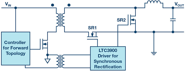 Figure 2. Synchronous rectification of a forward converter with a dedicated driver IC.
Figure 2 shows a way to implement synchronous rectification using the LTC3900. This is a controller for driving the synchronous rectification switches SR1 and SR2 in a forward topology.
Such a concept works well. However, the LTC3900 needs to prevent negative current flow through the external switches. First, the device needs to detect a negative current quickly and then the SR1 and SR2 switches need to be rapidly turned off. This is necessary to prevent damage to the circuit during a startup or during a possible burst mode.
Figure 2. Synchronous rectification of a forward converter with a dedicated driver IC.
Figure 2 shows a way to implement synchronous rectification using the LTC3900. This is a controller for driving the synchronous rectification switches SR1 and SR2 in a forward topology.
Such a concept works well. However, the LTC3900 needs to prevent negative current flow through the external switches. First, the device needs to detect a negative current quickly and then the SR1 and SR2 switches need to be rapidly turned off. This is necessary to prevent damage to the circuit during a startup or during a possible burst mode.
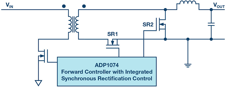 Figure 3. Synchronous rectification of a forward topology by complete integration with the ADP1074.
Figure 3 shows a very elegant circuit design with the new ADP1074. Output voltage information is sensed by the feedback pin. To prevent the risk of negative current flow across the SR1 and SR2 switches in certain circumstances, such as when there is precharge on the output capacitor, synchronous rectification is not activated. The body diodes of the two switches perform the rectification. In this way, damage to the switches can be prevented. The built-in iCoupler® technology in the ADP1074 enables safe operation without negative current flow.
Figure 3. Synchronous rectification of a forward topology by complete integration with the ADP1074.
Figure 3 shows a very elegant circuit design with the new ADP1074. Output voltage information is sensed by the feedback pin. To prevent the risk of negative current flow across the SR1 and SR2 switches in certain circumstances, such as when there is precharge on the output capacitor, synchronous rectification is not activated. The body diodes of the two switches perform the rectification. In this way, damage to the switches can be prevented. The built-in iCoupler® technology in the ADP1074 enables safe operation without negative current flow.
Author: Frederik Dostal studied microelectronics at the University of Erlangen-Nuremberg, Germany. Starting work in the power management business in 2001, he has been active in various applications positions, including four years in Phoenix, Arizona, working on switch mode power supplies. He joined © Analog Devices in 2009 and works as a power management technical expert for Europe.
Figure 1. Self-driven synchronous rectification of a forward converter.
Driving the switches for the synchronous rectification can be done in different ways. One simple concept for doing so involves driving across the transformer’s secondary winding. This is shown in Figure 1. In this example, the input voltage range may not be very wide. With the minimum input voltage, there needs to be enough voltage at the gates of SR1 and SR2 so that the switches can be reliably turned on. To ensure that the gate voltage at MOSFET SR1 and MOSFET SR2 does not exceed their maximum rated voltage, the maximum input voltage cannot be too high.
In all power supplies with synchronous rectification, a negative current may develop through the circuit. For example, if the capacitors at the output of the circuit are precharged before the circuit is turned on, current could flow from the output side to the input side. The negative current could increase the voltages at MOSFET SR1 and MOSFET SR2 in such a way that they might be damaged. Care must be taken to protect the switches in such an event.
Figure 2. Synchronous rectification of a forward converter with a dedicated driver IC.
Figure 2 shows a way to implement synchronous rectification using the LTC3900. This is a controller for driving the synchronous rectification switches SR1 and SR2 in a forward topology.
Such a concept works well. However, the LTC3900 needs to prevent negative current flow through the external switches. First, the device needs to detect a negative current quickly and then the SR1 and SR2 switches need to be rapidly turned off. This is necessary to prevent damage to the circuit during a startup or during a possible burst mode.
Figure 3. Synchronous rectification of a forward topology by complete integration with the ADP1074.
Figure 3 shows a very elegant circuit design with the new ADP1074. Output voltage information is sensed by the feedback pin. To prevent the risk of negative current flow across the SR1 and SR2 switches in certain circumstances, such as when there is precharge on the output capacitor, synchronous rectification is not activated. The body diodes of the two switches perform the rectification. In this way, damage to the switches can be prevented. The built-in iCoupler® technology in the ADP1074 enables safe operation without negative current flow.Author: Frederik Dostal studied microelectronics at the University of Erlangen-Nuremberg, Germany. Starting work in the power management business in 2001, he has been active in various applications positions, including four years in Phoenix, Arizona, working on switch mode power supplies. He joined © Analog Devices in 2009 and works as a power management technical expert for Europe.