

© janaka dharmasena dreamstime.com
Application Notes |
Using A2B for Audio-Conferencing Systems
One of the main hurdles in audio installation in a modern conference room these days is the need to interconnect a variety of input/output transducers into the main audio console. This is usually done using individual point-to-point shielded cables for each node, which is bulky and still requires separated external power supplies on each of them.
In addition to being bulky, these cables also carry analog audio signals that are subject to significant spectrum degradation, especially in long length installations or when electing to use cost-effective cable options. Transceiver chips for automotive audio buses, A2B®, support multichannel digital audio over a single unshielded twisted pair (UTP) wire. Multiple transceiver nodes can be daisy-chained and, in addition to transporting high fidelity digital audio, the A2B bus can transport a dc power supply to remote bus-powered nodes. Figure 1 depicts an A2B transceiver functional block diagram.
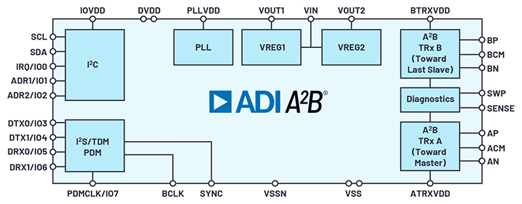 Figure 1. An A2B functional block diagram.
Although A2B transceiver technology was mainly designed to solve the problem of bulky audio cabling in automotive applications, it is certainly a much more generic audio transport method with a potential wide spread of applications. One such potential application for A 2B technology outside of automotive space is in huddle room conferencing systems. In a modern huddle room conferencing system, there is the need to distribute multiple microphones, and sometimes multiple speakers, around the room in order to implement a range of DSP functions such as beam forming, acoustic noise canceling, or echo canceling. Another possible application would be public auditoriums, assemblies, and places requiring simultaneous real-time translation. What really limits the A2B application in larger capacity rooms is the total cable length in one bus, which is limited to 40 meters overall.
Figure 1. An A2B functional block diagram.
Although A2B transceiver technology was mainly designed to solve the problem of bulky audio cabling in automotive applications, it is certainly a much more generic audio transport method with a potential wide spread of applications. One such potential application for A 2B technology outside of automotive space is in huddle room conferencing systems. In a modern huddle room conferencing system, there is the need to distribute multiple microphones, and sometimes multiple speakers, around the room in order to implement a range of DSP functions such as beam forming, acoustic noise canceling, or echo canceling. Another possible application would be public auditoriums, assemblies, and places requiring simultaneous real-time translation. What really limits the A2B application in larger capacity rooms is the total cable length in one bus, which is limited to 40 meters overall.
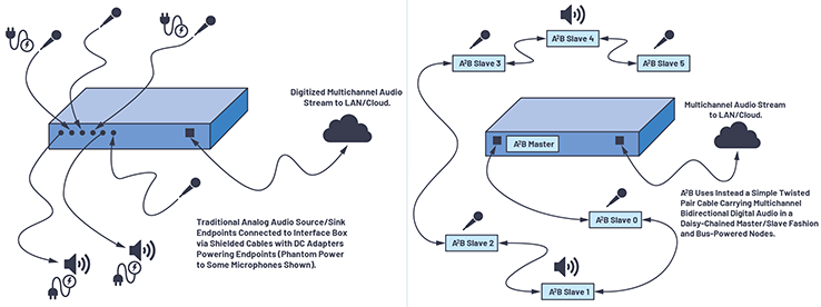 Figure 2. Traditional audio installation in a conference room. / Figure 3. Using A2B for audio installation in a conference room.
In such applications, A2B transceivers could be used to simplify the cabling of remote audio nodes while providing a superior digital transport method with optional power distribution. The prior method of connecting these remote audio nodes, as shown in Figure 2, was the use of shielded cables transporting a single analog signal in one direction per cable pair, with power being provided separately with a dc adapter. Meanwhile, a single twisted pair using A2B can transport up to 32 upstream and/or up to 32 downstream high fidelity digital audio channels plus bus power, as shown in Figure 3; when 16-bit data is used, the combined total number of channels in the bus is limited to 50 channels total. It is probably true that thesedesirable A2B features would bring enormous advantages if deployed in conferencing systems by simplifying cabling and adding bidirectional, high fidelity digital audio capabilities when compared to traditional analog methods.
Figure 2. Traditional audio installation in a conference room. / Figure 3. Using A2B for audio installation in a conference room.
In such applications, A2B transceivers could be used to simplify the cabling of remote audio nodes while providing a superior digital transport method with optional power distribution. The prior method of connecting these remote audio nodes, as shown in Figure 2, was the use of shielded cables transporting a single analog signal in one direction per cable pair, with power being provided separately with a dc adapter. Meanwhile, a single twisted pair using A2B can transport up to 32 upstream and/or up to 32 downstream high fidelity digital audio channels plus bus power, as shown in Figure 3; when 16-bit data is used, the combined total number of channels in the bus is limited to 50 channels total. It is probably true that thesedesirable A2B features would bring enormous advantages if deployed in conferencing systems by simplifying cabling and adding bidirectional, high fidelity digital audio capabilities when compared to traditional analog methods.
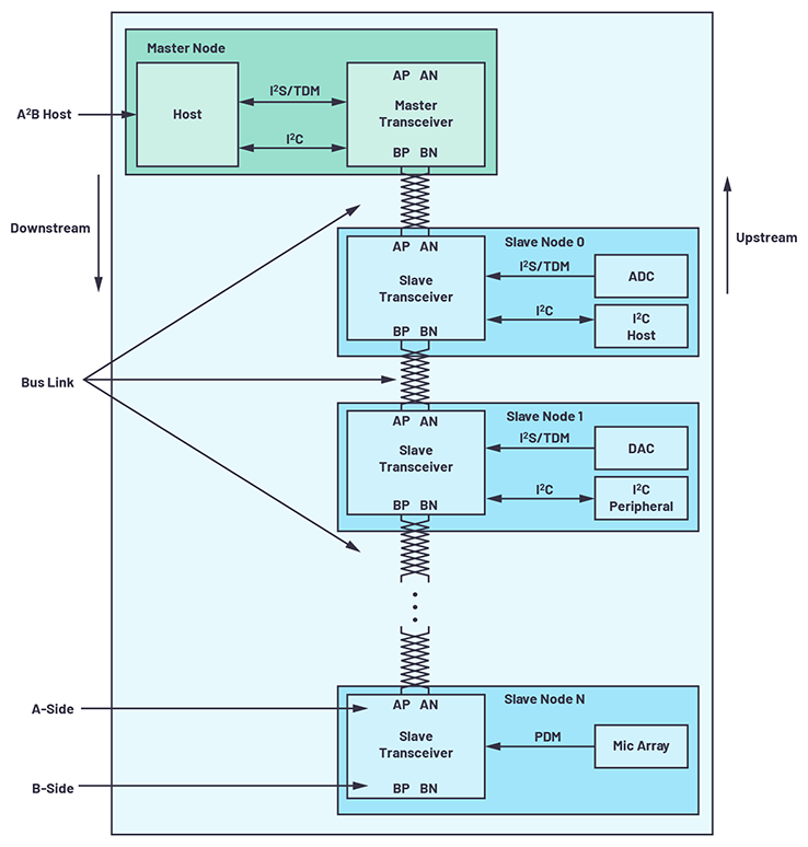 Figure 4. Simplified A2B system with four nodes (master node and three slave nodes).
The A2B transceiver connects multichannel inter-IC sound (I 2S) synchronous, pulse-code modulated (PCM) data over up to 15 meters between nodes and up to 40 meters overall length of all nodes. It also extends the synchronous, time-division multiplexed (TDM) nature of I2S to a system that connects multiple nodes where each node can consume data, provide data, or both. This data can include control functions in addition to audio content; for example, a GPIO on the A2B transceiver chip (up to 7 GPIO lines available on a typical A2B transceiver) can be connected to an LED on the microphone node and could be switched on/off remotely by the host in order to indicate an active (live) or inactive (muted) microphone.
Figure 4. Simplified A2B system with four nodes (master node and three slave nodes).
The A2B transceiver connects multichannel inter-IC sound (I 2S) synchronous, pulse-code modulated (PCM) data over up to 15 meters between nodes and up to 40 meters overall length of all nodes. It also extends the synchronous, time-division multiplexed (TDM) nature of I2S to a system that connects multiple nodes where each node can consume data, provide data, or both. This data can include control functions in addition to audio content; for example, a GPIO on the A2B transceiver chip (up to 7 GPIO lines available on a typical A2B transceiver) can be connected to an LED on the microphone node and could be switched on/off remotely by the host in order to indicate an active (live) or inactive (muted) microphone.
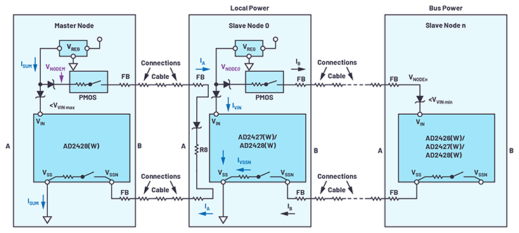 Figure 5. A dc power model for a system with local- and bus-powered slaves.
The A2B bus is a single-master, multiple-slave system where the transceiver chip at the host controller is the master. The master node generates clock, synchronization, and framing signaling for all slave nodes. The master A 2B chip is programmable over a control bus (I 2C) for configuration and read back. An extension of this control bus is embedded in the A2B data stream, allowing direct access of registers and status information on slave transceivers, as well as I 2C-to-I2C communication over distance.
Figure 5. A dc power model for a system with local- and bus-powered slaves.
The A2B bus is a single-master, multiple-slave system where the transceiver chip at the host controller is the master. The master node generates clock, synchronization, and framing signaling for all slave nodes. The master A 2B chip is programmable over a control bus (I 2C) for configuration and read back. An extension of this control bus is embedded in the A2B data stream, allowing direct access of registers and status information on slave transceivers, as well as I 2C-to-I2C communication over distance.
About the Author Carlos Martins works as a staff field applications engineer at © ADI, serving the Pacific Northwest region. Carlos acquired his B.S.E.E. from UFMG in Brazil and has about 30 years of design experience in system-level mixed-signal electronics. He was born in Rio de Janeiro and moved to the United States in the 1990s to fulfill his dream of working in the booming, high tech industry in Silicon Valley, CA. He can be reached at carlos.martins@analog.com.
Figure 1. An A2B functional block diagram.
Although A2B transceiver technology was mainly designed to solve the problem of bulky audio cabling in automotive applications, it is certainly a much more generic audio transport method with a potential wide spread of applications. One such potential application for A 2B technology outside of automotive space is in huddle room conferencing systems. In a modern huddle room conferencing system, there is the need to distribute multiple microphones, and sometimes multiple speakers, around the room in order to implement a range of DSP functions such as beam forming, acoustic noise canceling, or echo canceling. Another possible application would be public auditoriums, assemblies, and places requiring simultaneous real-time translation. What really limits the A2B application in larger capacity rooms is the total cable length in one bus, which is limited to 40 meters overall.
Figure 2. Traditional audio installation in a conference room. / Figure 3. Using A2B for audio installation in a conference room.
In such applications, A2B transceivers could be used to simplify the cabling of remote audio nodes while providing a superior digital transport method with optional power distribution. The prior method of connecting these remote audio nodes, as shown in Figure 2, was the use of shielded cables transporting a single analog signal in one direction per cable pair, with power being provided separately with a dc adapter. Meanwhile, a single twisted pair using A2B can transport up to 32 upstream and/or up to 32 downstream high fidelity digital audio channels plus bus power, as shown in Figure 3; when 16-bit data is used, the combined total number of channels in the bus is limited to 50 channels total. It is probably true that thesedesirable A2B features would bring enormous advantages if deployed in conferencing systems by simplifying cabling and adding bidirectional, high fidelity digital audio capabilities when compared to traditional analog methods.
Figure 4. Simplified A2B system with four nodes (master node and three slave nodes).
The A2B transceiver connects multichannel inter-IC sound (I 2S) synchronous, pulse-code modulated (PCM) data over up to 15 meters between nodes and up to 40 meters overall length of all nodes. It also extends the synchronous, time-division multiplexed (TDM) nature of I2S to a system that connects multiple nodes where each node can consume data, provide data, or both. This data can include control functions in addition to audio content; for example, a GPIO on the A2B transceiver chip (up to 7 GPIO lines available on a typical A2B transceiver) can be connected to an LED on the microphone node and could be switched on/off remotely by the host in order to indicate an active (live) or inactive (muted) microphone.
Figure 5. A dc power model for a system with local- and bus-powered slaves.
The A2B bus is a single-master, multiple-slave system where the transceiver chip at the host controller is the master. The master node generates clock, synchronization, and framing signaling for all slave nodes. The master A 2B chip is programmable over a control bus (I 2C) for configuration and read back. An extension of this control bus is embedded in the A2B data stream, allowing direct access of registers and status information on slave transceivers, as well as I 2C-to-I2C communication over distance.
A discovery mechanism is used when the system is powered up wherein each node is recognized and the TDM structure requirement is formed. All slave nodes are discovered sequentially from slave 0 to the last available slave in the system. Once all of the slave nodes are discovered, each node is then initialized for synchronous data exchange. Figure 4 shows a simple A2B system example with four nodes. The host program registers in each of the nodes to control the data traffic on the A2B bus. In this example, data from digital microphones and ADCs in slave nodes 0 and N are delivered to the master node while speaker data from the master node is simultaneously delivered to the DAC on slave node 1. As shown in this example, the A2B transceiver also incorporates a multichannel PDM interface for direct connection of pulse-density modulated microphone arrays. The number of audio channels per slave node can be individually programmable from up to 32 upstream channels and up to 32 downstream channels. Data slot sizes of 8, 12, 16, 20, 24, 28, or 32 bits can be used to match the I2S/TDM data word lengths, but this same slot size must be used for all nodes. Upstream and downstream can choose different slot sizes. Additionally, 12-, 16-, or 20-bit slot sizes can optionally carry compressed data over the A2B bus for 16-, 20-, or 24-bit I 2S/TDM word lengths. Audio sampling frequency (fSYNCM) can be set from 44.1 kHz to 48 kHz with all nodes synchronously sampling data. Slave nodes support sample rates (fS) of 1× (48 kHz), 2× (96 kHz), or 4× (192 kHz), which can be individually configured per slave. In order to support 2× and 4× sampling rates in slave nodes, the master node must use 2× and 4× the amount of I2S/TDM data channels at its 1× fSYNCM interface to the host. A2B transceivers also include robust error detection for control data and status data with a 16-bit CRC check. Another important feature available on A2B transceivers is fault diagnostics, where the transceiver can detect when an A 2B wire is shorted to a high voltage, shorted to ground, wires are shorted to each other, wires are reversed, or there is an open connection.Figure 6. EVAL-AD2428WD1BZ, A2B master- or local-power slave node (I2S/TDM, three PDM mics).
Figure 7. EVAL-AD2428WB1BZ, bus-powered A2B slave node (I2S/TDM, two PDM mics).
Figure 8. EVAL-AD2428WC1BZ, bus-powered A2B slave node (no I2S/TDM, four PDM mics).
In a bus-powered system, peripheral supply current draw has a direct impact on other nodes in the system. It is important to stay within the thermal package limits and not exceed the specification limits of IVSSN and VIN in any of the A 2B bus nodes (300 mA/100 mA at a 1.2 Ω IVSSN limit for the internal switch, depending on transceiver model, and a 9 V input voltage VIN maximum into its input regulator). The data sheet for the A 2B transceiver chip provides extensive examples of power budgeting calculations, and Figure 5 shows a model of a bus-powered system. While a rudimentary 2-wire cable is sufficient to establish A2B operation, proper selection of cables and connectors will make it possible to comply with the more stringent EMC test requirements commonly found in the industry. Suitable cable selection is needed in order to provide good electrical performance beyond typical spectral emissions ranges so that differential-to-common-mode transitions do not occur at harmonics of communication frequencies. A complete selection of evaluation boards allows design engineers to fully test and evaluate the performance of A 2B devices before committing to full design implementation. Here are some examples of available evaluation boards from ADI. Additional design resources on A2B technology by ADI can be found here.Figure 9. EVAL-AD2428WG1BZ, local-power A2B slave node (I2S/TDM, no PDM mics).
Figure 10. ADZS-AUDIOA2BAMP, A2B Class D amplifier module.
Figure 11. SHARC® audio module: an expandable hardware/software platform for audio applications.
About the Author Carlos Martins works as a staff field applications engineer at © ADI, serving the Pacific Northwest region. Carlos acquired his B.S.E.E. from UFMG in Brazil and has about 30 years of design experience in system-level mixed-signal electronics. He was born in Rio de Janeiro and moved to the United States in the 1990s to fulfill his dream of working in the booming, high tech industry in Silicon Valley, CA. He can be reached at carlos.martins@analog.com.