


© Analog Devices Inc.
Application Notes |
Orthogonal Perspectives
Question: I am using a MEMS inertial measurement unit (IMU) in a self-balancing guidance control system for a personal transportation platform. Can I expect a consumer targeted IMU to eliminate all misalignment errors between each sensor if all of the core sensor elements are on a single piece of silicon?
Answer:
No, this is generally not a safe expectation for your design. Industrial grade IMUs, which use robust discrete sensors with optimal packaging and caibration, offer much better alignment precision than consumer-targeted IMUs residing on a single piece of silicon.
Consumer targeted and industrial targeted IMUs tend to specify axis alignment behaviors differently. Consumer IMUs typically lump all misalignment errors into a single cross-axis sensitivity specification. Industrial targeted IMUs, such as the recently released ADIS16490, specify alignment precision more directly using two different specifications: axis-to-axis misalignment error and axis-to-package misalignment error. The axis-to-package misalignment error describes how well the alignment in each axis relates to mechanical features within the IMU package. Axis-to-axis misalignment error describes how well the alignment of each accelerometer and gyroscope axis fits into the ideal case of mutual orthogonality. This is why axis-to-axis misalignment error is also commonly known as orthogonal error.
We can see the mathematical relationship between cross-axis sensitivity (CAS) and axis-to-axis misalignment error (A2A_MAE) as described below:
CAS = sin(A2A_MAE)
A2A_MAE = asin(CAS)
The effect of nonorthogonality occurs between sensor axes, across sensors, or from package misalignment between the sensors and the enclosure. On an industrial targeted IMU, these specifications are fully described in the data sheet after factory calibration. For discrete components, the cross-axis sensitivity specification does not account for assembly variances to a PCB.
Ideally, multiple axes within gyroscopes and accelerometers are mutually orthogonal to each other. However, it is a common misconception that since a multi-axis gyroscope or accelerometer can be designed within one discrete MEMS component that each of the axes are perfectly orthogonal at 90° to one another. Although all inertial sensors in these devices are on a single piece of silicon, inherent errors introduced from fabrication and manufacturing variances can still accumulate an orthogonal error. The resulting equivalent alignment precision is actually not very impressive when compared to fully calibrated, industrial targeted IMUs.
A quick survey of consumer targeted devices reveals that cross-axis sensitivity is often in the range of 1% to 5%. Using the above relationship, that results in equivalent axis-to-axis misalignment errors of 0.57° to 2.87°. However, it could also be defined in units of milliradian, equal to 0.057°. Industrial grade IMUs will typically be much more precise. We can also use this relationship to translate the axis-to-axis misalignment error of an industrial targeted IMU of 0.018° into an equivalent cross-axis sensitivity of 0.031%.
CAS = sin(A2A_MAE) = sin(0.018°) = 0.00031 = 0.031%
Despite the apparent disadvantage of not having all inertial sensors on one piece of silicon, the ADIS16489 industrial grade IMU still offers ~32× better performance than the best consumer devices.
To understand the effect of nonorthogonal errors, let’s assume that one accelerometer axis is pointed perfectly upward and the device is exactly level. The accelerometer on this z-axis is ideally measuring the total impact of gravity. If the other two axes were perfectly orthogonal, they would not measure any vector of gravity.
However, if there is a nonorthogonality error, these two other horizontal axes would measure some portion of the gravity vector. For example, if a device offers a cross-axis sensitivity of 1%, its equivalent response to gravity will be 10 mg. This equates to an equivalent alignment error of 0.6°. Conversely,
if the first axis is not orthogonal to the level frame, it will measure less than the complete gravity vector.
Orthogonality errors are particularly stable components of the total error from an accelerometer. They may therefore yield to corrections based on a one time calibration. To determine the orthogonality error of accelerometer axis pairs, the static response of each axis to gravity is measured as the acceler-ometer is rotated through the space of all possible 90° orientations. This can be done using either a precision gimbal mount or on a known orthogonal surface.
It can be a challenging proposition to effectively calibrate out the orthogonal errors across the full operating conditions after mounting components onto a PCB. Inertial calibration requires observation of each sensor response, while the devices are experiencing well-controlled motion profiles. These types of motion profiles often require highly specialized equipment and expertise to operate effectively over time. In contrast to an industrial targeted IMU that is already precalibrated for mounting, each mounted consumer MEMS device on a PCB would need to be calibrated against the other sen-sors, environmental performance, and temperature.
Performance from an industrial IMU, composed of 3 gyroscope axes and 3 accelerometer axes, leverages a calibration step within manufacturing after discrete comp-onents are mounted on a mini-PCB in a rugged module. This single factory calibration identifies and compensates not only the nonorthogonality of the MEMS devices themselves, but also for any assembly related skew. This minimizes the errors associated with variances from assembly, cross-axis error, and temperature.
The ADIS16489 provides factory calibration that minimizes axis alignment errors within platform stabilization, navigation, or robotics applications. With a dig-ital tri-axis gyroscope and a tri-axis accelerometer, the ADIS16489 offers a mere ±0.018° axis-to-axis gyroscope misalignment error and ±0.035° accelerometer axis-to-axis error. In addition to the high performance sensor parameters, the ADIS16489 also provides a parylene coating as a moisture barrier for its internal circuitry.
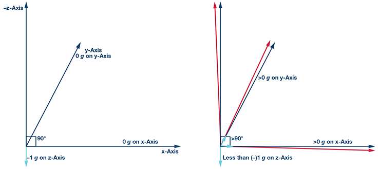 Figure 1. An ideal 3-axis orthogonal case on the left reflects the true impact of a vector. A nonorthogonal error allows leakage of rotation or force to be seen across all axes.
Author: Ian Beavers [ian.beavers@analog.com] is a product engineering manager for the Automation Energy and Sensors Team at © Analog Devices (Greensboro, NC). He has worked for the company since 1999. Ian has over 19 years of experience in the semiconductor industry. Ian earned a bachelor’s degree in electrical engineering from North Carolina State University and an M.B.A. from the University of North Carolina at Greensboro.
Figure 1. An ideal 3-axis orthogonal case on the left reflects the true impact of a vector. A nonorthogonal error allows leakage of rotation or force to be seen across all axes.Author: Ian Beavers [ian.beavers@analog.com] is a product engineering manager for the Automation Energy and Sensors Team at © Analog Devices (Greensboro, NC). He has worked for the company since 1999. Ian has over 19 years of experience in the semiconductor industry. Ian earned a bachelor’s degree in electrical engineering from North Carolina State University and an M.B.A. from the University of North Carolina at Greensboro.