


© Analog Devices Inc
Application Notes |
Sometimes, a Signal Needs to Ride the Rails
Question: I’m designing a signal conditioning block for a precision sensor analog front end. Should I use an op amp with rail-to-rail input?
Answer:
Possibly—it depends on if the output signal from the sensor forces the op amp to a voltage near the supply rails. For example, if we were to monitor a load current of 0 mA to 500 mA through a precision 10 Ω shunt resistor, the maximum output would be 5 V. If the amplifier supply voltage was 5 V, you would need to choose an amplifier with a rail-to-rail input voltage range.
 Figure 1. ADA4610 Typical input offset voltage vs. common-mode voltage.
The classic input stage of many op amps is a transistor differential pair. In order for the op amp to amplify the common-mode voltage (VCM) signal at the input, it must have sufficient voltage headroom between the VCM and the supply voltages. If VCM gets close enough to either supply rail so that the input pair runs out of headroom, the input offset voltage, as well as other key parameters, will be degraded, resulting in a loss of accuracy, as seen in Figure 1. It is these headroom requirements that define the op amp’s specified input voltage range (IVR). Some of the industry’s highest precision amplifiers, like the ADA4610, have this classic input structure. As long as the input voltage stays away from the rails, it has excellent precision.
Figure 1. ADA4610 Typical input offset voltage vs. common-mode voltage.
The classic input stage of many op amps is a transistor differential pair. In order for the op amp to amplify the common-mode voltage (VCM) signal at the input, it must have sufficient voltage headroom between the VCM and the supply voltages. If VCM gets close enough to either supply rail so that the input pair runs out of headroom, the input offset voltage, as well as other key parameters, will be degraded, resulting in a loss of accuracy, as seen in Figure 1. It is these headroom requirements that define the op amp’s specified input voltage range (IVR). Some of the industry’s highest precision amplifiers, like the ADA4610, have this classic input structure. As long as the input voltage stays away from the rails, it has excellent precision.
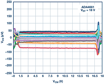 Figure 2. ADA4661: rail-to-rail op amp, typical input offset voltage vs. common-mode voltage.
If the sensor’s output signal does not include the V+ rail, but does range all the way down to the negative rail, it requires an amplifier that can accept a VCM that also goes to V–. This type of op amp is called single supply because, by tying the V– to ground, only one voltage source is required. Single-supply op amps use a special circuit topology that allows amplification of the signal even when it is near the V– rail.
Similarly, some applications require an op amp that maintains accuracy when the input ranges all the way from V– to V+. This is called a rail-to-rail input (RRI) op amp. These op amps typically combine two differential pairs—one for each rail. The ADA4661 is a classic example of a RRI op amp. As seen in Figure 2, it has excellent accuracy across the whole range of the supply voltages.
Figure 2. ADA4661: rail-to-rail op amp, typical input offset voltage vs. common-mode voltage.
If the sensor’s output signal does not include the V+ rail, but does range all the way down to the negative rail, it requires an amplifier that can accept a VCM that also goes to V–. This type of op amp is called single supply because, by tying the V– to ground, only one voltage source is required. Single-supply op amps use a special circuit topology that allows amplification of the signal even when it is near the V– rail.
Similarly, some applications require an op amp that maintains accuracy when the input ranges all the way from V– to V+. This is called a rail-to-rail input (RRI) op amp. These op amps typically combine two differential pairs—one for each rail. The ADA4661 is a classic example of a RRI op amp. As seen in Figure 2, it has excellent accuracy across the whole range of the supply voltages.
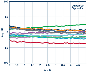 Figure 3. The ADA4500 rail-to-rail op amp eliminates distortion across its full supply range.
There are trade-offs when the input is comprised of two different pairs to create a rail-to-rail input. As VCM transitions from one pair to the other, a small crossover distortion is reflected in the offset voltage. In the ADA4661, you can see the distortion amplitude is about 50 µV and occurs about 2 V below the V+ rail. Although this may not be significant in some systems, we may need to avoid this distortion in others. One solution is to design the system so that the input voltage stays below the crossover voltage. In Figure 2, that would still give over 16 V of IVR. Applications with a low supply voltage (say 5 V) create a challenge since we can’t afford to give up enough IVR (say 2 V) without significantly reducing the voltage range of the input signal. In that application, we’ll need a different type of input stage.
The ADA4500 eliminates crossover, and therefore cross over distortion, by using a single input pair, combined with a charge pump that provides a higher internal voltage so that the pair has sufficient supply voltage, even when the op amp filter is at the rails. With this structure, the sensor can drive the op amp’s input voltage over the full supply range with no crossover distortion, as shown in Figure 3. While doing so, it delivers a guaranteed 95 dB of common-mode rejection and input offset voltage of 120 µV at 25°C for superior accuracy, even when the input signal has to ride the rails.
For a detailed discussion of op amp input structures and tradeoffs, see Mini Tutorial MT-035 “Op Amp Inputs, Outputs, Single-Supply, and Rail-to-Rail Issues” as well as the other references listed below.
Table 1. Selection of Precision Op Amps from Classic Rail-to-Rail (All Values Are in V)
Figure 3. The ADA4500 rail-to-rail op amp eliminates distortion across its full supply range.
There are trade-offs when the input is comprised of two different pairs to create a rail-to-rail input. As VCM transitions from one pair to the other, a small crossover distortion is reflected in the offset voltage. In the ADA4661, you can see the distortion amplitude is about 50 µV and occurs about 2 V below the V+ rail. Although this may not be significant in some systems, we may need to avoid this distortion in others. One solution is to design the system so that the input voltage stays below the crossover voltage. In Figure 2, that would still give over 16 V of IVR. Applications with a low supply voltage (say 5 V) create a challenge since we can’t afford to give up enough IVR (say 2 V) without significantly reducing the voltage range of the input signal. In that application, we’ll need a different type of input stage.
The ADA4500 eliminates crossover, and therefore cross over distortion, by using a single input pair, combined with a charge pump that provides a higher internal voltage so that the pair has sufficient supply voltage, even when the op amp filter is at the rails. With this structure, the sensor can drive the op amp’s input voltage over the full supply range with no crossover distortion, as shown in Figure 3. While doing so, it delivers a guaranteed 95 dB of common-mode rejection and input offset voltage of 120 µV at 25°C for superior accuracy, even when the input signal has to ride the rails.
For a detailed discussion of op amp input structures and tradeoffs, see Mini Tutorial MT-035 “Op Amp Inputs, Outputs, Single-Supply, and Rail-to-Rail Issues” as well as the other references listed below.
Table 1. Selection of Precision Op Amps from Classic Rail-to-Rail (All Values Are in V)
References
Author: Daniel Burton [daniel.burton@analog.com] is an applications engineer at © Analog Devices. He acquired his B.S.E.E. from San Jose State University and he has worked on sensing and precision linear signal paths for much of his career. Dan has been with Analog Devices since 2010, focusing on precision amplifiers and voltage references.
Figure 1. ADA4610 Typical input offset voltage vs. common-mode voltage.
The classic input stage of many op amps is a transistor differential pair. In order for the op amp to amplify the common-mode voltage (VCM) signal at the input, it must have sufficient voltage headroom between the VCM and the supply voltages. If VCM gets close enough to either supply rail so that the input pair runs out of headroom, the input offset voltage, as well as other key parameters, will be degraded, resulting in a loss of accuracy, as seen in Figure 1. It is these headroom requirements that define the op amp’s specified input voltage range (IVR). Some of the industry’s highest precision amplifiers, like the ADA4610, have this classic input structure. As long as the input voltage stays away from the rails, it has excellent precision.
Figure 2. ADA4661: rail-to-rail op amp, typical input offset voltage vs. common-mode voltage.
If the sensor’s output signal does not include the V+ rail, but does range all the way down to the negative rail, it requires an amplifier that can accept a VCM that also goes to V–. This type of op amp is called single supply because, by tying the V– to ground, only one voltage source is required. Single-supply op amps use a special circuit topology that allows amplification of the signal even when it is near the V– rail.
Similarly, some applications require an op amp that maintains accuracy when the input ranges all the way from V– to V+. This is called a rail-to-rail input (RRI) op amp. These op amps typically combine two differential pairs—one for each rail. The ADA4661 is a classic example of a RRI op amp. As seen in Figure 2, it has excellent accuracy across the whole range of the supply voltages.
Figure 3. The ADA4500 rail-to-rail op amp eliminates distortion across its full supply range.
There are trade-offs when the input is comprised of two different pairs to create a rail-to-rail input. As VCM transitions from one pair to the other, a small crossover distortion is reflected in the offset voltage. In the ADA4661, you can see the distortion amplitude is about 50 µV and occurs about 2 V below the V+ rail. Although this may not be significant in some systems, we may need to avoid this distortion in others. One solution is to design the system so that the input voltage stays below the crossover voltage. In Figure 2, that would still give over 16 V of IVR. Applications with a low supply voltage (say 5 V) create a challenge since we can’t afford to give up enough IVR (say 2 V) without significantly reducing the voltage range of the input signal. In that application, we’ll need a different type of input stage.
The ADA4500 eliminates crossover, and therefore cross over distortion, by using a single input pair, combined with a charge pump that provides a higher internal voltage so that the pair has sufficient supply voltage, even when the op amp filter is at the rails. With this structure, the sensor can drive the op amp’s input voltage over the full supply range with no crossover distortion, as shown in Figure 3. While doing so, it delivers a guaranteed 95 dB of common-mode rejection and input offset voltage of 120 µV at 25°C for superior accuracy, even when the input signal has to ride the rails.
For a detailed discussion of op amp input structures and tradeoffs, see Mini Tutorial MT-035 “Op Amp Inputs, Outputs, Single-Supply, and Rail-to-Rail Issues” as well as the other references listed below.
Table 1. Selection of Precision Op Amps from Classic Rail-to-Rail (All Values Are in V)
| Precision Op Amp | Headroom from V+ | Headroom from V– | Supply Range | Input Structure |
| ADA4610 | 2.5 | 2.5 | 10 to 36 | Classic differential pair |
| ADA4522 | 1.5 | 0 | 4.5 to 55 | Single supply |
| ADA4622 | 1 | –0.2 | 10 to 30 | Single supply |
| ADA4084 | 0 | 0 | 3 to 30 | Rail-to-rail |
| ADA4661 | 0 | 0 | 3 to 18 | Rail-to-rail |
| ADA4505 | 0 | 0 | 1.8 to 5 | Zero crossover distortion |
| ADA4500 | 0 | 0 | 2.7 to 5.5 | Zero crossover distortion |
- Analog Devices Mini Tutorial MT-035 “Op Amp Inputs, Outputs, Single-Supply, and Rail-to-Rail Issues”
- Ardizzoni, John. “Single Supply Amplifiers—They Sound Simple…are they?” Analog Dialogue, Volume 38, October 2008.
- Ardizzoni, John. “Is Amplifier Headroom Cramping Your Style?”
- Analog Dialogue, Volume 62, October 2010.
Author: Daniel Burton [daniel.burton@analog.com] is an applications engineer at © Analog Devices. He acquired his B.S.E.E. from San Jose State University and he has worked on sensing and precision linear signal paths for much of his career. Dan has been with Analog Devices since 2010, focusing on precision amplifiers and voltage references.