The introduction of PSS alters the traditional approach of verifying and validating a system on chip (SoC), offering many advantages and a few challenges. This paper explores these process changes with the life cycle of an interconnect bus fabric from SystemC-based performance analysis to verification and validation using a generic PSS-based traffic generator.
Introduction
Verification techniques and methodologies have continually evolved ever since the design requirements have started becoming complex. The portable stimulus standard (PSS) is the latest addition to this evolution process and it was created to address the challenge of test portability. The new PSS allows creation of the test intent such that it can be reused across different target platforms. Along with portability, the PSS-based verification techniques also offer value in terms of visual test representation, constraint setting, dataflow-based randomization, and higher test quality. There is a subsequent process change involved in the SoC verification and validation process with the adoption of PSS-based techniques and it is important to understand its impact. This paper tries to explore these process changes with a case study of an interconnect bus fabric starting from SystemC-based performance analysis to verification and validation.
Detailed Description
As designs become more and more complex, the process changes like SystemC-based modeling, architectural explorations, and high level synthesis (HLS) are becoming common along with traditional design and integration flows. These process changes, in turn, introduce the requirements of checking adherence to the system design requirements. Different teams involved in these processes have different kinds of platforms and languages to support these changes. But despite this difference, the basic specifications of each successive process is the same, which leads to a lot of duplicated effort.
The architectural development team creates a virtual platform for architectural exploration and software development using SystemC- and TLM-based modeling. The component design team designs the Verilog components at block level and integrates them to create a system either manually or with an automated process. Verification at the IP level is typically done using UVMbased verification, while at the system level, a combination of C- and UVM-based approaches is used. The UVM environment allows the checkers to be easily reused from the IP level to the system level, but the test stimulus is often rewritten to work in the top level UVM environment or in C to run on the processor at the chip level. The effort to create tests verifying the startup/configuration and basic mode operation of blocks is repeated for actual silicon testing as new tests are required for the test platform or to run on an evaluation board. Then, the software teams make another effort to write the software drivers for the customer interface.
These duplications of efforts across teams using different languages and techniques result in frequent false bug reports and significantly inflate the overall time to market. A better solution is needed to allow all the test writers throughout the project to speak a common language and allow a large portion of the simple functional verification tests to be seamlessly reused both horizontally and vertically. This different approach is exactly what the PSS-based verification techniques bring to the table.
The PSS defines a new test writing language that will allow the automatic creation of tests targeted to different platforms from a single test source. In addition to horizontal reuse (simulation, emulation, board level, tester, etc.), the new language will allow vertical reuse of tests as well. The tests developed at the IP level would be more easily integrated and reused at the SoC level.
The portable stimulus works at a higher layer of abstraction that is completely independent from the type of target platform. The target platform here can be a UVM-based verification environment, a C/C++-based and an SoC-based environment, a C- and Python®-based post-silicon evaluation platform, and so forth.
The PSS-based application provides exciting opportunities to create generic applications, which can be used to verify the test intent at various levels. One similar opportunity arises when we use an interconnect bus fabric in a multiprocessor SoC. There are various levels where we need to verify and evaluate the functionality and performance.
The interconnect bus fabric needs to be chosen wisely as per the specific requirements of the SoC and hence an early performance analysis is required, which can be done using system models (typically in C/SystemC). This requires the creation of tests that can verify the system models. Once the choice of its configuration is made and RTL is generated, it needs to be verified at the IP level. This requires UVM-based verification and UVM sequences to verify the same. Subsequently, the generated RTL is integrated within the SoC system level and it needs to be verified at the SoC level. This is typically done by coding tests in C/C++ for verification and validation.
All these interconnect verification applications can be handled by creating reusable tests using PSS-based techniques. To accomplish this, a PSS model was created for a generic traffic generator, which can create different patterns of read and write for a different number of masters. The traffic generator can generate traffic with different distributions to each master so that fast and slow masters can be emulated.
Also, it can independently control which master generates traffic and at what frequency, as well as create back-to-back and delayed transactions. Figure 1 shows the process flow with a PSS-based traffic generator. The blocks in purple represent the interconnect bus with generic slaves and masters, while the blocks in green represent the RTL, or behavioral models, which drive the transactions on the bus. The PSS-based traffic generator (represented in pink) integrates and controls these blocks to drive and collect transactions. The traffic generator handles different kinds of traffic generation requirements and creates tests for various targets like SystemC-based applications, UVM, and C-based tests. Each process needs to be handled differently in terms of integration and test generation, which will be described in the subsequent sections.
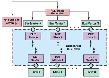 Figure 1. PSS-based process flow for performance analysis and verification of the interconnect bus.
SystemC-Based Performance Analysis of Interconnect Bus
Figure 1. PSS-based process flow for performance analysis and verification of the interconnect bus.
SystemC-Based Performance Analysis of Interconnect Bus
The performance analysis of the interconnect bus is carried out to quantitatively measure the system performance and power as early as possible in the SoC development cycle. The performance of an interconnect bus needs to be evaluated for a wide range of applications, platforms, and interconnect configurations (topology, features, configuration, etc.). It involves gathering requirements, creating specifications, and then taking those specifications and turning them into a cohesive design that matches the requirements for performance, power, and area. This is an iterative process that is performed over the course of design. With every iteration, the specifications need to be captured and communicated to design and development teams.
This is achieved with SystemC-based representative TLM models of the given SoC specification that can be used to accurately predict the system’s behavior. Figure 2 shows this flow, starting from configuring the tool for generating the SystemC models. These models are part of the tool kit, which can be configured to suit the needs of the design. It can be used to generate cycle accurate or approximate models for AMBA masters and slaves, clock generators, and stimuli. Once the models are in place, the traffic pattern needs to be written at this level, either manually or with directed automated scripts to convert the specification into actual simulation and gather results. The models are then simulated using specific simulators that help provide a solution to quantify the performance.
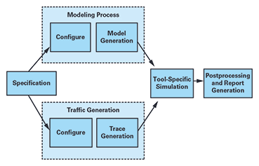 Figure 2. Performance analysis flow using SystemC modeling.
Despite having modeling and analysis tools, using the tool for more than a handful of candidate designs can be time consuming. The use of scripts to generate traffic provides certain kinds of traffic patterns, but exhaustive scenario generation is still a problem. On top of it, as the simulations are time consuming, doing the analysis at the end of the simulation increases the number of trials to achieve the expected numbers. Coupled with the time spent on specification management across the design and the performance modeling functions, we see that there is a need for a more automated flow that starts with a single source. The PSS-based techniques are an effective way to address these challenges.
The randomization mechanism in PSS-based tools starts from an abstract description of the legal transitions between the high level states of the DUT and automatically enumerates the minimum set of tests needed to cover the paths through this state space. The PSS-based tools have a coverage mechanism that can measure how exhaustively the conditions have been covered in the given state space. This allows the measurement of the coverage even before any of the generated stimuli have been run, thus saving time in the process. The PSS-based coverage allows the user to view the transverse paths and allows tests to be generated such that the maximum length of the graph is covered. It is thus able to achieve higher coverage in far fewer cycles than the usual constrained random verification.
The PSS-based tools also provide a visual representation of the test intent that allows better visualization of the scenarios that can be generated. The directed tests for covering specific test conditions can be easily transverse with this feature. It also allows the constraining of certain sets of conditions, thus creating constrained random scenarios for specific feature set. The introduction of PSS-based techniques essentially keeps the flow as given in Figure 2, but the trace generation flow is changed considerably.
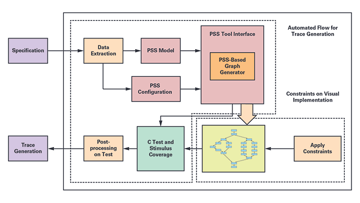 Figure 3. PSS-based flow to generate traffic patterns.
The heart of the traffic generator is a generic PSS model that contains the algorithm to generate different kinds of traffic patterns. It is a single representation of stimulus and test scenarios. This model can be configured in different ways to generate tests that contain one of several permutations possible to generate traffic. It consists of three parts:
- Exec blocks: The exec blocks are statements from the external code used in target platforms under the PSS-based wrapper. For the SystemC-side application, it has custom code that will perform different types of reads and writes to the underlying environment. For the UVM SV part, it has logic derived from tool-provided macros (transceiver generation) that translates and interacts with the SV world with PLI-based system calls. It also has a part (C generation) that can translate and interact with C side and allows seamless reuse across different platforms.
- PSS model: This is the actual use case model based on an entire set of specifications. It consists of a collection of functions that will be the equivalent of higher level sequences to perform a set of actions. The traffic generator contains different sets of algorithms, which are represented in the form of various simple and compound actions. These functions will eventually call the functions from the exec blocks to execute commands on the SV side.
- PSS configuration: The models being generic needs specific information to generate specific tests. This can be information related to verification like the number of AMBA masters, slaves, master type, source and destination address, access type, mean bandwidth, burst size, data size, frequency, and bandwidth requirements. This information needs to be derived from the specification to generate a correct representation of the test intent.
Figure 3 represents the PSS-based traffic pattern generation flow, which starts with the parsing of the specification. A Pythonbased script parses certain aspects of specifications written in the spreadsheets and extracts the data in a certain format that can be read by the generic PSS model and configuration. The PSS model and configuration are then parsed by the PSS tools to create a visual representation of the test intent.
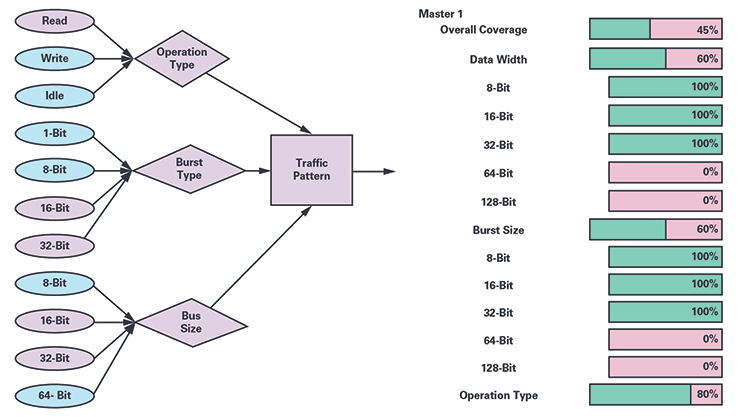 Figure 4. Visual representation of the test intent and PSS-based coverage.
Figure 4 shows some part of the visual representation of the test intent. It has the conditions represented as write or read operations, single or Burst Mode®, different bus sizes, etc., which can be controlled to generate different types of traffic patterns. The parts in purple are represented as the conditions that will be transverse, while the ones in blue will not be taken into consideration. This helps the user to visualize and constrain different aspects of required traffic. If the user doesn’t add constraints, the PSS tools randomly select certain configurations and create constrained random tests. This is also a point where tool-based coverage can be collected and an early analysis of completeness can be made. The tool-based coverage is a measure of how well the test intent has been covered in the tool generated tests. Figure 4 represents parts of the PSS-based coverage generated by the PSS tools. The blocks in pink represent the conditions not covered, while the green represents the conditions that have been covered. The user can look at this representation and create the tests for the conditions which are not covered.
Table 1. Summary of Data Collected with the PSS Simulation
|
|
| Experiment ID | Master | Slave | Direction | Mean Simulated Bandwidth | Mean Static Bandwidth | Mean Simulated Latency
|
| 5000 | Core | SMMR | Read | 1199.72 | 6000 | 24
|
| 5001 | Core | SMMR | Write | 999.79 | 6000 | 24
|
| 5002 | Core | L2 mem | Write | 99.92 | 100 | 24
|
| 5003 | Core | L2 mem | Read | 99.92 | 100 | 21.34 |
Once the tests are generated, a postprocessing script is run to create the traffic pattern compatible with the performance analysis simulation tool in its custom format. The next step is to run the simulations and generate traffic to produce a vast amount of raw data which must be processed into different metrics and visualizations to support effective analysis of the results. Table 1 shows a few examples of the report generated with parameters considered for calculating the performance analysis of the interconnect bus for an SoC with multiple masters and slaves. This analysis can have one (master)-to-one (slave) and many-to-one simulations (termed as experiments) to be generated based on a platform specification. Experiments are generated based on a static analysis of the clock frequencies and data widths defined in the platform specification, configured to run up to their theoretical maximum bandwidth.
In general, the PSS-based traffic allows better placement of the random scenarios targeted for a specific bus configuration. Also, the visual representation of the test intent allows the generation of better constraints. The ability to visualize coverage leads to better traffic patterns, thus fewer iterations to reach the highest possible bandwidth in a given master-slave system.
We have seen an improvement in terms of the number of iterations required to reach the highest mean simulated bandwidth with the adoption of PSS-based techniques, thus saving simulation cycles and analysis time.
By reducing the work required to make architectural performance models of the interconnect, as well as a single source of truth in a unified specification, any reconfiguration time is significantly reduced. The flow allows us to explore many design candidates before settling on one to run through timing closure and RTL flows.
UVM-Based Verification of Interconnect Bus
The performance analysis of the interconnect fabric gives out the best configuration in terms of performance, power, and area. Once the interconnect configuration is frozen, it can be used to generate AMBA interconnect RTL with a configurable automated flow. But this flow can be error prone, owing to configuration limitations, software structure, and manual interpretation of the specifications, thus it needs to be verified to ascertain a flawless generation process. This is achieved traditionally by using the industry standard UVM-based approach.
The UVM environment for verification of the interconnect bus is shown in Figure 5. It consists of a different kind of AMBA (AXI, AHB, APB) master and UVC slave in custom configurations connected to the DUT slaves and masters, respectively. The environment can be configured with a generic configuration for the environment. The scoreboard records the transactions and indicates error on any kind of data mismatch.
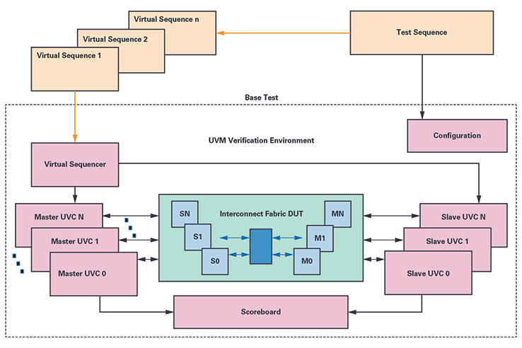 Figure 5. UVM-based IP verification of interconnect bus.
The tests contain sets of sequences and virtual sequences that control the functionality of the underlying UVC and interfaces. The tests are run in accordance with the test plan derived from the specifications with the directed and random test cases. The functional coverage points are also created with respect to the verification plan to ensure we meet the specification. After this, the simulations are run and a coverage database is created to collect code and functional coverage. The database is analyzed and coverage holes are reviewed. The regressions are run, and reports are generated and analyzed. The process is repeated until the desired coverage goals are reached to ensure high quality verification.
Along with the directed tests as a part of the verification plan, the UVM-based technique relies upon the random tests to achieve the coverage goals. It starts with random stimuli and gradually tightens the constraints until coverage goals are met, relying on the brute power of randomization and compute server farms to cover the state space. While the code coverage is the quantitative measure, the functional coverage is the qualitative measure of the DUT code execution. Typically, this quality is limited by the diligence and thoroughness of the people who draw up the verification plan and analyze the coverage reports. The other factor that decides the quality of verification is the effective automated checking. A combination of packet comparison using the scoreboards and assertion-based checkpoints can decide the number of post-silicon bugs discovered later in the flow. The UVMbased verification technique is self sufficient and effective in ensuring high quality verification. However, the introduction of PSS-based techniques further improves the verification flow with its various features.
The PSS-based verification starts with the creation of the verification plan as per design specification and the setting up of the verification environment. The test intent is captured in terms of portable stimulus models, constraints, and configuration files. The tools supporting this standard can then generate the tests for a given type of verification environment and graph-based coverage is collected. The analysis of this type of coverage can indicate the holes in the test constraints and configuration and the process can be revisited.
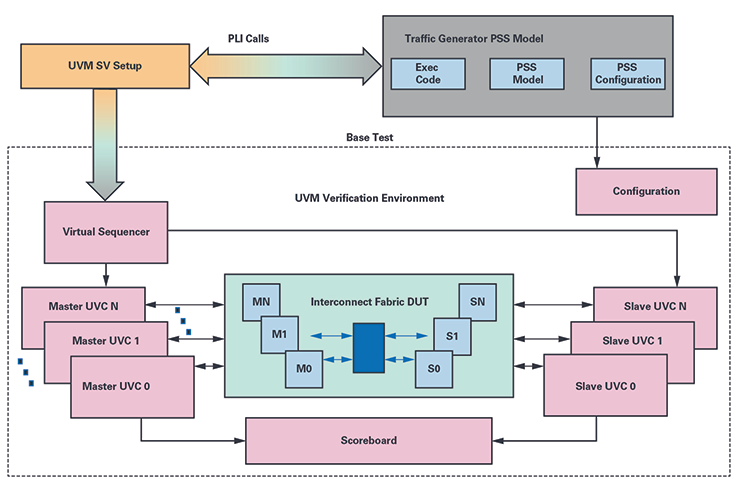 Figure 6. PSS-based IP verification of the interconnect bus.
Figure 6 shows the verification flow with the introduction of PSS-based models. The important point to note here is that the PSSbased models don’t replace the UVM-based environment. Instead, it adds on to the existing UVM-based environment to enhance its capabilities. The UVM verification environment continues to have the master and slave UVCs, with the SB and configuration while the virtual sequences are bypassed with the UVM SV infrastructure. The environment is controlled by a top level UVM test, which on one hand calls the virtual sequences to control the UVC operation, and on the other hand it interacts with the portable stimulus generated format with PLI- or DPI-based system calls. The PSS model is completely reused from the SystemC-based performance modeling process. The testing logic generated from the PSS-based model controls all the operations between the UVCs. The IP level simulations are run using the generated tests and coverage is collected.
Table 2 shows the results of regression run with PSS- and UVM-based verification environments. The number of constrained random tests run to achieve the maximum coverage possible (with waivers) reduces significantly with the adoption of a UVMbased approach. The randomization mechanism in PSS-based verification starts from an abstract description of the legal transitions between the high level states of the DUT and automatically enumerates the minimum set of tests needed to cover the paths through this state space. The graph-based coverage allows the user to view the transverse paths and allows tests to be generated such that maximum length of the graph is covered.
Table 2. PSS UVM Setup and Regression
|
|
| Tests Run | Passed | Failed | Not Run | Overall Code Coverage
|
| (UVM only) 125 | 125 | 0 | 0 | 298034/388949 (76.6%)
|
| (UVM PSS) 75 | 75 | 0 | 0 | 298034/388949 (76.6%) |
The test quality is another factor that can be better controlled by the portable stimulus verification methodology. The test can be visually seen, allowing users to understand the control and data flows in a better way. Also, some tools allow active checks to be placed during the run-time, allowing effective automated checking. This would combine with the scoreboard checking and assertion-based checkpoints, improving the quality of verification.
The portable stimulus methodology works at a higher layer of abstraction and then integrates with the underlying verification process. Due to this, although there is a definite improvement in the test or stimulus generation process, this verification methodology would still inherit the underlying process in its original form. In the case of integration with UVM-based environments, on one hand it will be benefitted by the reuse of verification components, and on the other hand, it will be limited by its complexity. Similarly, as is the case with UVM, the quality of verification is limited by the quality of the verification plan and analysis of the coverage reports.
SoC Verification of Interconnect Bus
When the interconnect is integrated as a part of the SoC, it is vital to check its integration with the various masters and slaves in the system. This is typically done with the C-based tests that run on the processor to check the integration of the interconnect bus. The generic masters at the IP level changes to specific bus masters like multiple processors, DSP, DMA controllers, serial protocol masters like SPI, I2C, CAN, and many more custom masters and slaves. This asks for specific sequences or macros meant to control the different masters and the slaves in the SoC. The macros or sequences will typically have register programming to enable the transmit and receive transactions from masters like DMA controllers, memories, etc. There is no constrained randomization at this level, so each scenario needs to be explored and written manually. In terms of reuse, some of the UVM monitors from the IP level can be used to monitor the protocol or scoreboards to check specific points of interest. But the tests and the sequences that contain major parts of the specifications need to be redone in C with a different focus.
 Figure 7. PSS-based SoC verification of the interconnect bus.
The PSS-based verification techniques are designed for the IP to SoC test reuse. Figure 7 shows the reuse of the traffic generator PSS models at the SoC level verification. The models coded at the IP level are configured for different address maps as per SoC specification and targeted for C test generation. The same set of sequences written at the IP level with the graph-based constrained randomization are possible to reuse. Almost all the sequences in the model—with exception of the parts meant for exec code—are reusable when we write model for the processor-based applications. Having said that, the exec code in this case is substantially more complex including complete enable and disable macros for a variety of masters such as DMA and memory controllers that can initiate the single or burst transactions on the interconnect bus. For every generic master, the exec code needs to be rewritten so that it can integrate with the variety of masters in the SoC. The tool randomization allows multiple combinations of master and slave transactions. The constrains for creating directed tests for integration checks at the SoC level can be managed well with the visual representation of the test. Once the C tests are generated, they are integrated with the SoC setup with some system specific standard infrastructure. The C tests are then compiled and run on the processor to generate transactions.
Figure 7 also shows the creation of multicore tests with the PSS tools, which are difficult to write manually. Different parts of test intent can be targeted to run on different cores, allowing interesting scenario creation. It is specifically helpful in this case where multiple bus masters exist. The programming of different masters becomes possible due to this feature set. The ability to reproduce graph-based constrained random tests at the SoC level without the need to actually recode the scenarios is a major advantage as well. It also allows the test generation to examine different instances of the same IP with different address maps. Along with this, when different kinds of PSS models for different IPs are combined at the SoC level, the creation of complex scenarios is possible when they would otherwise be difficult to code manually.
Validation of Interconnect Bus
The validation process is required to establish product compliance to the customer’s specification, usability, and acceptance testing. Traditionally, an evaluation board requires C-based tests that are manually written from the original specification. This duplication of effort can be greatly reduced by using a PSS-based approach where C tests compatible with the evaluation software can be generated.
Figure 8 represents the validation process with the PSS-based approach. The PSS model for the traffic generator can be configured for different address maps as per SoC specification and targeted for Eval-C tests generation. The PSS tools typically have the ability to generate tests for multiple cores, which enable specific scenario testing as well. The generated C tests are compiled by the debuggers and code is loaded on the evaluation board with interfaces like JTAG. The tests can be run and results can be seen on the evaluation board and debugger interface. The same set of sequences written at the SoC level with the graph-based constrained randomization are completely possible to reuse. In addition to this, the visual representation of the test intent and ability to apply constraints comes in handy to create directed scenarios. This is a unique and controlled way to create tests in the validation process which has traditionally been completely manual.
Here again, the exec code needs to be rewritten for silicon-validation specific requirements. The basic software drivers from the validation platform used to control different masters on the bus such as DMA and memory controllers can typically be used for this kind of application. The generated C code also needs to be integrated in a format that is acceptable to the evaluation platforms. Typically, this process includes reusing the header and taking files from a prewritten validation code and reusing them in the generated integration code. The code is then compiled and run with the target debugger to ensure proper testing at this level.
The PSS tools typically provide the ability to analyze the results of the run with postprocessing applications. The visual analysis of the results indicating test pass or fail with specific segments of the code yielding results is possible. This is especially helpful in the validation process because traditional debugging capabilities are very limited here.
Although we haven’t reused the C tests for the traffic generator model at the post-silicon-based application yet, we are confident that it can be used on any evaluation platform employing C-based tests. In fact, the kinds of models where SoC-based PSS models are reused for post-silicon evaluation boards have been proven for other processor-based applications. This reuse is the kind of application which is unique to portable stimulus-based approaches only.
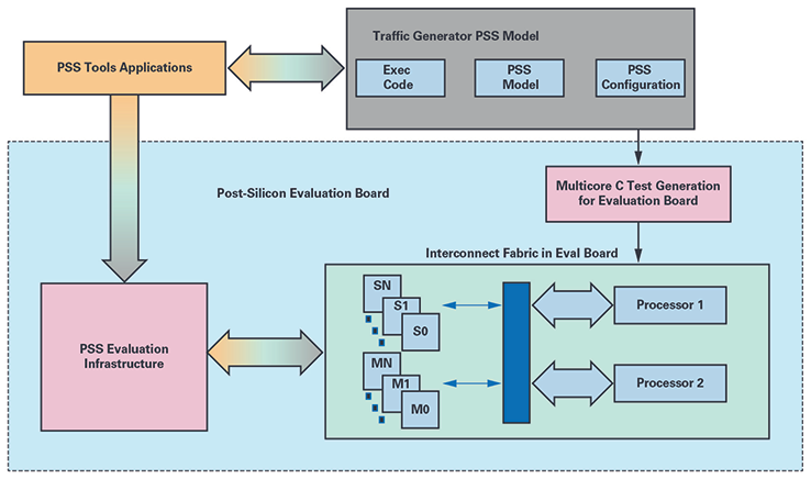 Figure 8. PSS-based silicon validation of the interconnect bus.
Summary
Figure 8. PSS-based silicon validation of the interconnect bus.
Summary
The PSS-based generic traffic generator allows test reuse for the interconnect bus from SystemC-based performance analysis to verification and validation processes. There is a need for integration and infrastructure development for each of the processes. But this is a one-time process and offers a possibility for reuse in subsequent applications. Along with reuse, the PSS-based approach offers advantages in terms of specific randomization, visual representation of test intent, and an early coverage analysis, adding further value. The ability to create generic applications allows the possibility of plug-and-play solutions, which can further accelerate the verification and validation process.
References
- Ajamian, Tom. “AMBA Interconnect Design Flow Automation.” Synopsys, Inc., 2015.
- Bhatnagar, Gaurav and David Brownell. “Portable Stimulus vs. Formal vs. UVM: A Comparative Analysis of Verification
- Methodologies Throughout the Life of an IP Block.” DVCon, 2018.
- Portable Stimulus Working Group. Accellera Systems Initiative, 2019.
- TrekUVM™ : Eliminating UVM Overhead. Breker Verification Systems, 2019.
- UVM (Standard Universal Verification Methodology). Accellera Systems Initiative, 2019.
About the Authors
Gaurav Bhatnagar is a staff design verification engineer in the Engineering Enablement (EE) Group. He is an electronics engineer with 15 years of experience and joined © ADI in 2015. He has been working on universal, formal, and portable stimulus verification methodologies. He can be reached at gaurav.bhatnager@analog.com.
Courtney Fricano is a staff design verification engineer in the Engineering Enablement (EE) Group. She leads the verification subteam of the engineering systems and verification center of excellence. Courtney has a bachelor’s degree from Penn State University and a master’s degree from MIT. She can be reached at courtney.fricano@analog.com