

© janaka dharmasena dreamstime.com_technical
Application Notes |
Solving the Cable TV Infrastructure Downstream Transmitter Challenge
Driven by demand for faster internet connectivity, the cable TV industry has developed new network architectures for the delivery of multigigabit services to subscribers. This fiber deep approach, using a remote PHY device (RPD), moves critical hardware closer to the users by using digital fiber.
This is comparable with a remote radio head in wireless (cellular) networks and while this saves space and reduces heat dissipation in the headend, it creates new design challenges for remote equipment.
Although lower in absolute frequency, cable TV signals have much wider bandwidths than wireless, extending across several octaves from 108 MHz to 1218 MHz, with multiple in-band harmonics. RPDs have created a perfect storm for designers, where the RF and mixed-signal hardware must cover a wider frequency range, with higher RF powers, lower noise floor, and better linearity, while consuming less dc power. The downstream final stage RF amplifiers each typically draw 18 W, and with a 4-port system, this is around 50% of the 140 W to 160 W power budget that can typically be delivered to (and dissipated by) an RPD.
ADI’s cable digital predistortion (DPD) efficiency enhancement technology, applied to a DPD optimized power doubler (ADCA3992), combined with advances in high speed data converter technology allows a single DAC (such as the AD9162), and a single ADC (such as the AD9208), complemented by a highly integrated clocking solution (HMC7044) make full-band DPD a reality.
This article describes the evolution to remote PHY and how Analog Devices has solved the efficiency and linearity challenge, using a proprietary DPD, with ADI’s algorithms and IP core integrated within the OEM’s existing FPGA implementation.
Background
Since its introduction as community access television (CATV) more than 60 years ago, cable TV has evolved from a simple unidirectional (downstream only) analog link to a complex multimode, multichannel bidirectional system (including upstream or reverse path) that supports analog TV, IP-based standard definition (SD) and high definition (HD) digital TV, and high speed data for internet download and upload. These services are provided by multiple system operators (MSOs).
Cable data and digital TV services are delivered to consumers using the data over cable systems interface specification (DOCSIS), which was developed by CableLabs and contributing companies. There have been multiple evolutions in the configuration of the headend (cable modem termination system or CMTS), including the addition of EdgeQAM modulators either as a separate unit or integrated with the CMTS as part of a converged cable access platform (CCAP). The demand for downstream data capacity is now increasing at a compound annual growth rate (CAGR) of around 50%, meaning that demand doubles roughly every 21 months.1 To meet this demand, since the release of DOCSIS 1.0 in 1997, downstream data rates have increased from 40 Mbps through to 1.2 Gbps (with the widely deployed DOCSIS 3.0 implementation).
These downstream speed increases were implemented through the combination of multiple techniques including channel bonding, more complex modulation (moving from 64 QAM to 256 QAM) and higher downstream upper frequency limit (from 550 MHz to 750 MHz to 1002 MHz). In the United States, all of this was implemented while retaining the 6 MHz channel plan from the legacy analog TV service (8 MHz for EuroDOCSIS and C-DOCSIS), but to support downstream rates up to 10 Gbps, it became necessary to make changes that are more fundamental, and in 2013 the DOCSIS 3.1 standard was published. While it maintains support for legacy standards, DOCSIS 3.1 uses the more spectrally efficient orthogonal frequency division multiplexing (OFDM) technique, with channel bandwidths of up to 190 MHz supporting up to 4096 QAM. Additionally, the upper frequency limit of the downstream frequency range was increased by more than 20% to 1218 MHz, with an option for extending to 1794 MHz.
One thing that has not changed over time is the use of a coaxial cable with 75 Ω impedance for the physical link to subscribers’ cable modems. Prior to the 1990s, systems used 100% coaxial cable between the headend and the subscriber, but most current deployments are hybrid fiber copper (HFC). In HFC, an analog electrical-to-optical converter is connected to the headend’s coaxial output; the signal is then transferred to a node close to the service area using fiber, and then passed through an optical-to-electrical converter for final distribution to subscribers over coaxial cable. This last-mile connection to the subscriber, with overhead or underground cable, has become a bottleneck in the system, but upgrading to a fiber to the home (FTTH) link is very expensive and disruptive, and cable MSOs are determined to make the most of their existing coaxial cable assets. Compared to twisted pair telephone cable, coaxial cable presents a relatively benign environment, with inherent shielding from interference or crosstalk, and modest levels of signal reflections due to impedance mismatch. However, with a typical distance from the node to the most distant subscriber of up to 1200 feet, the frequency dependent loss characteristics are significant (there is a slope of almost 17 dB between 108 MHz and 1002 MHz), requiring pre-emphasis or tilt, implemented by RF filter inserts with a high-pass response.
In a typical HFC deployment, as shown in Figure 1, a single trunk coaxial cable connected from the optical node feeds several hundred subscribers, with multiway RF splitters to distribute the signal to subgroups and taps to connect drop cables to the individual subscribers. In a typical node + n system, wideband booster amplifiers are inserted into the network at regular intervals to increase the signal level to ensure adequate signal-to-noise ratio (SNR) at the cable modem.
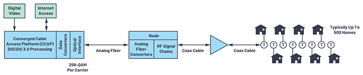 Figure 1. Cable TV deployment with HFC.
Providing Increased Data Capacity to Subscribers
The available data bandwidth on a DOCSIS trunk cable is shared between all the connected users, and there are two options for providing more bandwidth to all users:
Figure 1. Cable TV deployment with HFC.
Providing Increased Data Capacity to Subscribers
The available data bandwidth on a DOCSIS trunk cable is shared between all the connected users, and there are two options for providing more bandwidth to all users:
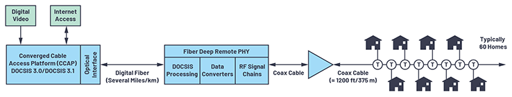 Figure 2. Cable TV deployment with remote PHY.
Digital fiber offers considerably higher performance than analog fiber, with longer reach (providing more flexibility in determining node locations) and support for around five times more wavelengths on a single fiber. The DAA approach also eliminates the electrical-to-optical and optical-to-electrical conversions from thetraditional HFC network. These transitions constrain the dynamic range of the signal at the output of the optical node: both the noise floor and linearity of the analog conversions impact the modulation error ratio (MER), which determines the ability to support the high order modulations required for high data rates.
The Challenges?
Fiber deep architectures will offer improved capacity on a per user basis through a much smaller serving group size, more freedom of spectral allocation, and better end-of-line SNR and MER (essential for the high order modulation in DOCSIS 3.1 ). With digital fiber and new hardware located relatively close to subscribers, opportunities for complementary services are also made possible such as the addition of Wi-Fi access points at the remote PHY nodes. However, several new design challenges are created in the downstream analog transmit chain.
The DOCSIS 3.1 standard extends the downstream upper frequency limit from 1002 MHz to 1218 MHz, meaning that the equivalent of 35 additional 6 MHz channels must be transmitted, and the degree of uptilt, shown in Figure 3, increases from 17 dB to 21 dB.
Figure 2. Cable TV deployment with remote PHY.
Digital fiber offers considerably higher performance than analog fiber, with longer reach (providing more flexibility in determining node locations) and support for around five times more wavelengths on a single fiber. The DAA approach also eliminates the electrical-to-optical and optical-to-electrical conversions from thetraditional HFC network. These transitions constrain the dynamic range of the signal at the output of the optical node: both the noise floor and linearity of the analog conversions impact the modulation error ratio (MER), which determines the ability to support the high order modulations required for high data rates.
The Challenges?
Fiber deep architectures will offer improved capacity on a per user basis through a much smaller serving group size, more freedom of spectral allocation, and better end-of-line SNR and MER (essential for the high order modulation in DOCSIS 3.1 ). With digital fiber and new hardware located relatively close to subscribers, opportunities for complementary services are also made possible such as the addition of Wi-Fi access points at the remote PHY nodes. However, several new design challenges are created in the downstream analog transmit chain.
The DOCSIS 3.1 standard extends the downstream upper frequency limit from 1002 MHz to 1218 MHz, meaning that the equivalent of 35 additional 6 MHz channels must be transmitted, and the degree of uptilt, shown in Figure 3, increases from 17 dB to 21 dB.
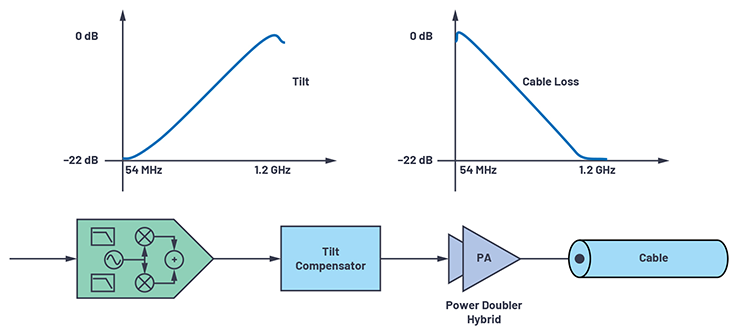 Figure 3. Tilt compensation for frequency dependent cable loss.
Since any new system needs to retain compatibility with existing deployments, and the power in the highest DOCSIS 3.0 channel (centered at 999 MHz) must remain unchanged (typically 57 dBmV), this means that the RF power required in the highest channel (centered at 1215 MHz) will be 61 dBmV. With the additional channels, increased tilt, and the need for high SNR at the cable modem, the output signal level demanded from the Class A ultralinear power amplifier (power doubler hybrid), which is the final active component before the node’s output port, has more than doubled to a composite level of 76.8 dBmV. To meet this increased RF power demand, hybrid designers have had to increase the per hybrid dc bias power from around 10 W to 18 W and, in some cases, to increase the dc supply voltage from an industry-standard value of 24 V to 34 V. Since nodes typically support up to four RF ports, each with its own hybrid, and are commonly powered from a 60 V ac supply injected through the coaxial cable, this has forced significant design changes and created new thermal management problems.
In order to support the higher order QAM profiles with DOCSIS 3.1, the most demanding MER requirement at the node output has increased from 43 dB to 48 dB.2 With such high MER requirements, the phase noise and spurious signals on the DAC clock can begin to have an impact on system performance. The main impairments in the power doubler, which directly affect both MER and in-band and out-of-band distortion, are nonlinear distortions, both harmonic and intermodulation. With a multioctave operating range from 108 MHz to 1218 MHz, there are multiple inband even and odd order harmonics, and with 185 D3.0 carriers (or equivalent), there is a very complex set of IM products. Tilt also has a significant impact as the power in the upper channels is more than 100 times greater than the power in the lowest channels and significant difference frequency products can fall here. Peak-to-average power ratios (PAPRs) can exceed 12 dB.
All of these factors combine to create a major challenge for power doubler designers: wider bandwidth, higher average and peak power, and improved linearity. The latest Class A GaAs/GaN push-pull hybrids, such as the ADCA3992, can meet the bandwidth, RF power, and linearity requirements, but the challenge for the RF system designer is undoubtedly reducing the power consumption and power dissipation: with a dc input of around 18 W dc for an RF output power of 650 mW (equivalent to 76.8 dBmV composite ), the dc-to-RF efficiency is only 3.6%.
What Is the System Solution?
Once the hybrid can support the required bandwidth and power, the first part of the solution is to ensure that the power doubler hybrid, which is the final active component before the output port, is fed with a clean signal. Using a high performance wideband 16-bit RF DAC, such as the AD9162, and a low phase noise, low spurious emission JESD204B-compatible clock source, such as the HMC7044, it is possible to achieve around 52 dB MER at the DAC output across the entire DOCSIS 3.1 frequency range.
The second part of the solution is more complex. Ideally, any solution would simultaneously increase the power doubler’s output power capability and improve MER, while reducing power dissipation, but these are almost mutually exclusive: reducing dissipation will degrade MER at a constant output power or require the RF power to be backed-off for MER to remain constant. While techniques such as envelope tracking (ET) could be used to improve efficiency, creating the very wide bandwidth envelope signal and linearizing the significant distortion created by the ET process will introduce extra challenges.
For a combination of efficiency enhancement and MER improvement, the most attractive solution is DPD, which is almost universally adopted across the wireless cellular industry. DPD allows the user to operate the power doubler hybrid in a more efficient, but more nonlinear region, and then preemptively correct for the distortions in the digital domain before the data is sent to the amplifier. As shown in Figure 4, the action of DPD is to shape the data before it gets to the amplifier to counteract the distortions the amplifier will produce, which extends the linear range of the power doubler.
Figure 3. Tilt compensation for frequency dependent cable loss.
Since any new system needs to retain compatibility with existing deployments, and the power in the highest DOCSIS 3.0 channel (centered at 999 MHz) must remain unchanged (typically 57 dBmV), this means that the RF power required in the highest channel (centered at 1215 MHz) will be 61 dBmV. With the additional channels, increased tilt, and the need for high SNR at the cable modem, the output signal level demanded from the Class A ultralinear power amplifier (power doubler hybrid), which is the final active component before the node’s output port, has more than doubled to a composite level of 76.8 dBmV. To meet this increased RF power demand, hybrid designers have had to increase the per hybrid dc bias power from around 10 W to 18 W and, in some cases, to increase the dc supply voltage from an industry-standard value of 24 V to 34 V. Since nodes typically support up to four RF ports, each with its own hybrid, and are commonly powered from a 60 V ac supply injected through the coaxial cable, this has forced significant design changes and created new thermal management problems.
In order to support the higher order QAM profiles with DOCSIS 3.1, the most demanding MER requirement at the node output has increased from 43 dB to 48 dB.2 With such high MER requirements, the phase noise and spurious signals on the DAC clock can begin to have an impact on system performance. The main impairments in the power doubler, which directly affect both MER and in-band and out-of-band distortion, are nonlinear distortions, both harmonic and intermodulation. With a multioctave operating range from 108 MHz to 1218 MHz, there are multiple inband even and odd order harmonics, and with 185 D3.0 carriers (or equivalent), there is a very complex set of IM products. Tilt also has a significant impact as the power in the upper channels is more than 100 times greater than the power in the lowest channels and significant difference frequency products can fall here. Peak-to-average power ratios (PAPRs) can exceed 12 dB.
All of these factors combine to create a major challenge for power doubler designers: wider bandwidth, higher average and peak power, and improved linearity. The latest Class A GaAs/GaN push-pull hybrids, such as the ADCA3992, can meet the bandwidth, RF power, and linearity requirements, but the challenge for the RF system designer is undoubtedly reducing the power consumption and power dissipation: with a dc input of around 18 W dc for an RF output power of 650 mW (equivalent to 76.8 dBmV composite ), the dc-to-RF efficiency is only 3.6%.
What Is the System Solution?
Once the hybrid can support the required bandwidth and power, the first part of the solution is to ensure that the power doubler hybrid, which is the final active component before the output port, is fed with a clean signal. Using a high performance wideband 16-bit RF DAC, such as the AD9162, and a low phase noise, low spurious emission JESD204B-compatible clock source, such as the HMC7044, it is possible to achieve around 52 dB MER at the DAC output across the entire DOCSIS 3.1 frequency range.
The second part of the solution is more complex. Ideally, any solution would simultaneously increase the power doubler’s output power capability and improve MER, while reducing power dissipation, but these are almost mutually exclusive: reducing dissipation will degrade MER at a constant output power or require the RF power to be backed-off for MER to remain constant. While techniques such as envelope tracking (ET) could be used to improve efficiency, creating the very wide bandwidth envelope signal and linearizing the significant distortion created by the ET process will introduce extra challenges.
For a combination of efficiency enhancement and MER improvement, the most attractive solution is DPD, which is almost universally adopted across the wireless cellular industry. DPD allows the user to operate the power doubler hybrid in a more efficient, but more nonlinear region, and then preemptively correct for the distortions in the digital domain before the data is sent to the amplifier. As shown in Figure 4, the action of DPD is to shape the data before it gets to the amplifier to counteract the distortions the amplifier will produce, which extends the linear range of the power doubler.
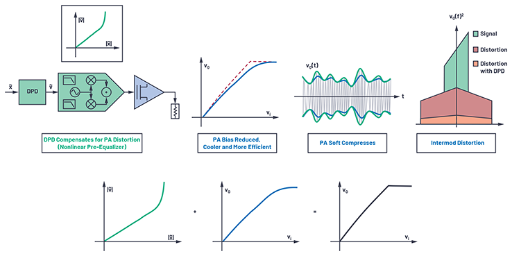 Figure 4. Digital predistortion.
With an extended linear operating range, DPD provides an additional degree of freedom to allow the amplifier to run at a reduced bias current or supply voltage (reducing power dissipation) or to improve MER and the bit error rate (BER), and a combination of the two is even possible. Although DPD has been widely used in wireless cellular infrastructures, implementing DPD in a cable environment has unique and challenging requirements. These include applying linearization over an ultrawide bandwidth, minimizing the power dissipation in the digital signal processing required to implement DPD, and operating with a highly tilted spectrum. All of this has to be achieved with only modest changes (and cost increases) to the hardware, FPGA, and software.
Since efficiency is improved by driving the amplifier into a nonlinear operating region, the multiple in-band distortion products present a unique challenge for the DPD. It is not just the large signal bandwidth, but also its positioning on the spectrum (just 108 MHz from dc), that poses a challenge to DPD. The nature of the cable signal is very different from wireless, where the bandwidth of the wanted signal (for example, 60 MHz) is much less than the RF center frequency (for example, 2140 MHz). In a typical 108 MHz to 1218 MHz DOCSIS 3.1 downstream allocation, the wanted signal bandwidth is 1110 MHz, with a center frequency of 663 MHz. Harmonic distortion occurs in all nonlinear systems; the focus of cable DPD is the in-band harmonic distortion products. In typical wireless systems, the third- and fifth-order harmonics are most important as the other products fall out of band and can be removed through conventional filtering. In a typical cable deployment, the first 11 harmonics of the lowest carrier fall in band.
In contrast to wireless cellular where only the odd order harmonics are of concern, within the cable application both the even and odd terms fall in band, creating multiple, overlapping zones of distortion. This has some serious implications for the complexity and sophistication of any DPD solution as the algorithm must move past simple narrow-band assumptions. The DPD solution must accommodate terms for each order of harmonic distortion. Each order k requires [k/2] + 1 terms (second order: k = 2 → 2 terms, third order: k = 3 → 2 terms, fourth order: k = 4 → 3 terms, etc.). In a narrow-band system, the even order terms can be ignored, and the odd orders produce one term each within the band of interest. DPD in the cable application must concern itself with both odd and even order harmonic distortions and consider that each order can have multiple overlapping in-band elements.
Positioning the Harmonic Distortion Corrections
Considering a conventional narrow-band DPD solution where processing is done at complex baseband, we are principally concerned with harmonic distortions that sit symmetrically around the carrier. In wideband cable systems, although that symmetry is maintained for those terms located around the first harmonic, it no longer holds for the higher harmonic products.
Figure 4. Digital predistortion.
With an extended linear operating range, DPD provides an additional degree of freedom to allow the amplifier to run at a reduced bias current or supply voltage (reducing power dissipation) or to improve MER and the bit error rate (BER), and a combination of the two is even possible. Although DPD has been widely used in wireless cellular infrastructures, implementing DPD in a cable environment has unique and challenging requirements. These include applying linearization over an ultrawide bandwidth, minimizing the power dissipation in the digital signal processing required to implement DPD, and operating with a highly tilted spectrum. All of this has to be achieved with only modest changes (and cost increases) to the hardware, FPGA, and software.
Since efficiency is improved by driving the amplifier into a nonlinear operating region, the multiple in-band distortion products present a unique challenge for the DPD. It is not just the large signal bandwidth, but also its positioning on the spectrum (just 108 MHz from dc), that poses a challenge to DPD. The nature of the cable signal is very different from wireless, where the bandwidth of the wanted signal (for example, 60 MHz) is much less than the RF center frequency (for example, 2140 MHz). In a typical 108 MHz to 1218 MHz DOCSIS 3.1 downstream allocation, the wanted signal bandwidth is 1110 MHz, with a center frequency of 663 MHz. Harmonic distortion occurs in all nonlinear systems; the focus of cable DPD is the in-band harmonic distortion products. In typical wireless systems, the third- and fifth-order harmonics are most important as the other products fall out of band and can be removed through conventional filtering. In a typical cable deployment, the first 11 harmonics of the lowest carrier fall in band.
In contrast to wireless cellular where only the odd order harmonics are of concern, within the cable application both the even and odd terms fall in band, creating multiple, overlapping zones of distortion. This has some serious implications for the complexity and sophistication of any DPD solution as the algorithm must move past simple narrow-band assumptions. The DPD solution must accommodate terms for each order of harmonic distortion. Each order k requires [k/2] + 1 terms (second order: k = 2 → 2 terms, third order: k = 3 → 2 terms, fourth order: k = 4 → 3 terms, etc.). In a narrow-band system, the even order terms can be ignored, and the odd orders produce one term each within the band of interest. DPD in the cable application must concern itself with both odd and even order harmonic distortions and consider that each order can have multiple overlapping in-band elements.
Positioning the Harmonic Distortion Corrections
Considering a conventional narrow-band DPD solution where processing is done at complex baseband, we are principally concerned with harmonic distortions that sit symmetrically around the carrier. In wideband cable systems, although that symmetry is maintained for those terms located around the first harmonic, it no longer holds for the higher harmonic products.
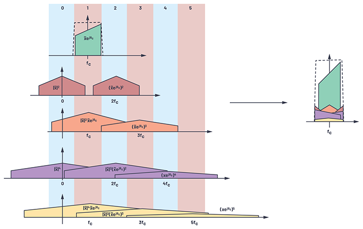 Figure 5. The effects of broadband harmonic distortion in wideband cable applications.
As shown in Figure 6a, conventional narrow-band DPD is implemented at complex baseband. In these instances, only the first harmonic products fall in band such that their baseband representation translates directly to RF. When we consider wideband cable DPD (Figure 6b), the higher harmonic distortions must be frequency offset so that the baseband representations after upconversion are positioned correctly in the real RF spectrum.
Figure 5. The effects of broadband harmonic distortion in wideband cable applications.
As shown in Figure 6a, conventional narrow-band DPD is implemented at complex baseband. In these instances, only the first harmonic products fall in band such that their baseband representation translates directly to RF. When we consider wideband cable DPD (Figure 6b), the higher harmonic distortions must be frequency offset so that the baseband representations after upconversion are positioned correctly in the real RF spectrum.
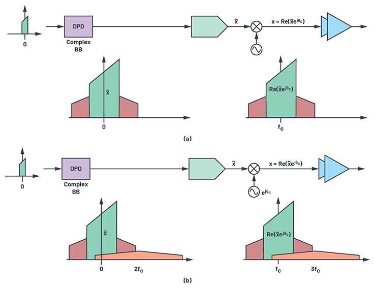 Figure 6. Frequency offset requirements in the complex baseband processing for wideband DPD. (a) Conventional narrow-band DPD processing done at complex baseband. (b) Wideband cable DPD, OOB HD must be frequency offset to allow for RF upconversion.
Figure 7 provides an overview of a DPD implementation. In an ideal situation, the path from the digital upconverter (DUC) via the DPD to the DAC and through the power doubler will have no bandwidth restrictions. Likewise, the ADC on the observation path will digitize the full bandwidth. Note that for illustration purposes, a 2× bandwidth signal path is shown; in some wireless cellular applications, that may extend to 3× to 5×. The ideal implementation has the DPD produce terms both in-band and out of band that totally cancel the distortion introduced by the PA. It is important to note that for accurate cancellation, terms are created well outside the bandwidth of the signal of interest. In a practical implementation, the signal path has bandwidth limitations and tilt characteristics that modify the DPD performance from ideal.
Analog Devices has developed a complete real-time, closed-loop, adaptive DPD solution for cable, consisting of an actuator in the FPGA fabric and software-based adaptation in the embedded processor. The implementation uses an Intel ® Arria® 10 660 FPGA, with an embedded ARM® Cortex® processor. The power consumption of the DPD IP core and ARM is 5.3 W, although with newer generations of FPGA or transition to ASIC this power is expected to be below 3 W.
Figure 6. Frequency offset requirements in the complex baseband processing for wideband DPD. (a) Conventional narrow-band DPD processing done at complex baseband. (b) Wideband cable DPD, OOB HD must be frequency offset to allow for RF upconversion.
Figure 7 provides an overview of a DPD implementation. In an ideal situation, the path from the digital upconverter (DUC) via the DPD to the DAC and through the power doubler will have no bandwidth restrictions. Likewise, the ADC on the observation path will digitize the full bandwidth. Note that for illustration purposes, a 2× bandwidth signal path is shown; in some wireless cellular applications, that may extend to 3× to 5×. The ideal implementation has the DPD produce terms both in-band and out of band that totally cancel the distortion introduced by the PA. It is important to note that for accurate cancellation, terms are created well outside the bandwidth of the signal of interest. In a practical implementation, the signal path has bandwidth limitations and tilt characteristics that modify the DPD performance from ideal.
Analog Devices has developed a complete real-time, closed-loop, adaptive DPD solution for cable, consisting of an actuator in the FPGA fabric and software-based adaptation in the embedded processor. The implementation uses an Intel ® Arria® 10 660 FPGA, with an embedded ARM® Cortex® processor. The power consumption of the DPD IP core and ARM is 5.3 W, although with newer generations of FPGA or transition to ASIC this power is expected to be below 3 W.
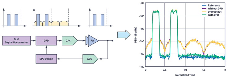 Figure 7. Idealized DPD implementation with no bandwidth restrictions.
Results
Figure 8 shows the results of a test with an ADCA3992 operating at 76.8 dBmV total composite power, with a supply voltage of 34 V and a bias current of 400 mA (13.6 W dc power).
Figure 7. Idealized DPD implementation with no bandwidth restrictions.
Results
Figure 8 shows the results of a test with an ADCA3992 operating at 76.8 dBmV total composite power, with a supply voltage of 34 V and a bias current of 400 mA (13.6 W dc power).
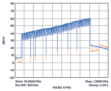 Figure 8. ADCA3992 performance at 76.8 dBmV without DPD (blue) and with DPD (orange).
The test signal is a series of DOCSIS 3.0 carriers centered from 111 MHz to 1215 MHz with 21 dB tilt. A small number of gaps were introduced to allow the distortion across the band to be viewed. It can be observed that the distortion at the bottom of the band is improved by around 6 dB, with more than 8 dB at the top of the band.
The dc power saving compared to a nominal non-DPD power doubler current of 530 mA is 4.4 W, so with a 4-port system, the total power saving is 17.6 W minus the FPGA power of 5.3 W, resulting in a net saving of 12.3 W. This is a significant reduction in power consumption (and heat dissipation) for a 4-port system from 72 W to 59.7 W. It is likely that the bias current for each doubler could be further backed-off to 350 mA (11.9 W) while still meeting a target MER of 41 dB, resulting in a net system saving of 19.2 W.
Conclusion
Despite the increasing availability of high speed mobile data and fiber to the premises, the massive footprint of existing last-mile networks, and their relatively benign electrical characteristics, ensures that they will remain an important vehicle for the delivery of voice, video, and data services to consumers for the foreseeable future. As cable networks transition to DOCSIS 3.1 and its evolutions, meeting system performance requirements, such as wider frequency range, higher power, better modulation accuracy, and higher power efficiency becomes ever more difficult.
DPD provides a means to address these conflicting requirements, although its implementation in the cable application poses unique and difficult challenges. ADI has developed a total system solution to address these challenges, which encompasses mixed-signal silicon (DACs, ADCs, and clocks), RF power modules (GaN/GaAs hybrids), and advanced algorithms. The combination of all three technologies provides equipment manufacturers with a high performance adaptable solution with the flexibility to trade off power consumption and system performance with minimal compromise. Software-defined linearization also supports a straightforward transition to the next generation of cable technologies that are expected to incorporate full duplex (FD), extended bandwidth (to 1794 MHz), and envelope tracking (ET).
The author would like to thank Patrick Pratt for the DPD diagrams.
References
1 Robert L. Howald. “The Fiber Frontier.” Spring Technical Forum Proceedings, 2016.
2 Data-Over-Cable Service Interface Specifications, DOCSIS® 3.1—Physical Layer Specification: CM-SP-PHYv3.1-I08-151210. CableLabs, May 2017.
About the Author
Simon Whittle is a technical program manager for the Wireless Systems Group within the Communications Business Unit. He is based at © Analog Devices’ Bath (UK) office, where he leads projects on systems for cable TV and 5G millimeter wave. Before joining ADI in July 2012, Simon worked in the cellular infrastructure industry, leading teams developing technology for 3G and 4G remote radio heads. Prior to this he developed receivers and high power transmitters for cellular, mobile radio, and broadcast applications, for which he holds several patents. He graduated from the University of Surrey in 1983 and is an IEEE member. He can be reached at simon.whittle@analog.com.
Figure 8. ADCA3992 performance at 76.8 dBmV without DPD (blue) and with DPD (orange).
The test signal is a series of DOCSIS 3.0 carriers centered from 111 MHz to 1215 MHz with 21 dB tilt. A small number of gaps were introduced to allow the distortion across the band to be viewed. It can be observed that the distortion at the bottom of the band is improved by around 6 dB, with more than 8 dB at the top of the band.
The dc power saving compared to a nominal non-DPD power doubler current of 530 mA is 4.4 W, so with a 4-port system, the total power saving is 17.6 W minus the FPGA power of 5.3 W, resulting in a net saving of 12.3 W. This is a significant reduction in power consumption (and heat dissipation) for a 4-port system from 72 W to 59.7 W. It is likely that the bias current for each doubler could be further backed-off to 350 mA (11.9 W) while still meeting a target MER of 41 dB, resulting in a net system saving of 19.2 W.
Conclusion
Despite the increasing availability of high speed mobile data and fiber to the premises, the massive footprint of existing last-mile networks, and their relatively benign electrical characteristics, ensures that they will remain an important vehicle for the delivery of voice, video, and data services to consumers for the foreseeable future. As cable networks transition to DOCSIS 3.1 and its evolutions, meeting system performance requirements, such as wider frequency range, higher power, better modulation accuracy, and higher power efficiency becomes ever more difficult.
DPD provides a means to address these conflicting requirements, although its implementation in the cable application poses unique and difficult challenges. ADI has developed a total system solution to address these challenges, which encompasses mixed-signal silicon (DACs, ADCs, and clocks), RF power modules (GaN/GaAs hybrids), and advanced algorithms. The combination of all three technologies provides equipment manufacturers with a high performance adaptable solution with the flexibility to trade off power consumption and system performance with minimal compromise. Software-defined linearization also supports a straightforward transition to the next generation of cable technologies that are expected to incorporate full duplex (FD), extended bandwidth (to 1794 MHz), and envelope tracking (ET).
The author would like to thank Patrick Pratt for the DPD diagrams.
References
1 Robert L. Howald. “The Fiber Frontier.” Spring Technical Forum Proceedings, 2016.
2 Data-Over-Cable Service Interface Specifications, DOCSIS® 3.1—Physical Layer Specification: CM-SP-PHYv3.1-I08-151210. CableLabs, May 2017.
About the Author
Simon Whittle is a technical program manager for the Wireless Systems Group within the Communications Business Unit. He is based at © Analog Devices’ Bath (UK) office, where he leads projects on systems for cable TV and 5G millimeter wave. Before joining ADI in July 2012, Simon worked in the cellular infrastructure industry, leading teams developing technology for 3G and 4G remote radio heads. Prior to this he developed receivers and high power transmitters for cellular, mobile radio, and broadcast applications, for which he holds several patents. He graduated from the University of Surrey in 1983 and is an IEEE member. He can be reached at simon.whittle@analog.com.
Figure 1. Cable TV deployment with HFC.
Providing Increased Data Capacity to Subscribers
The available data bandwidth on a DOCSIS trunk cable is shared between all the connected users, and there are two options for providing more bandwidth to all users:
- Increase the data rate passed through the cable
- Reduce the number of users connected to the cable
Figure 2. Cable TV deployment with remote PHY.
Digital fiber offers considerably higher performance than analog fiber, with longer reach (providing more flexibility in determining node locations) and support for around five times more wavelengths on a single fiber. The DAA approach also eliminates the electrical-to-optical and optical-to-electrical conversions from thetraditional HFC network. These transitions constrain the dynamic range of the signal at the output of the optical node: both the noise floor and linearity of the analog conversions impact the modulation error ratio (MER), which determines the ability to support the high order modulations required for high data rates.
The Challenges?
Fiber deep architectures will offer improved capacity on a per user basis through a much smaller serving group size, more freedom of spectral allocation, and better end-of-line SNR and MER (essential for the high order modulation in DOCSIS 3.1 ). With digital fiber and new hardware located relatively close to subscribers, opportunities for complementary services are also made possible such as the addition of Wi-Fi access points at the remote PHY nodes. However, several new design challenges are created in the downstream analog transmit chain.
The DOCSIS 3.1 standard extends the downstream upper frequency limit from 1002 MHz to 1218 MHz, meaning that the equivalent of 35 additional 6 MHz channels must be transmitted, and the degree of uptilt, shown in Figure 3, increases from 17 dB to 21 dB.
Figure 3. Tilt compensation for frequency dependent cable loss.
Since any new system needs to retain compatibility with existing deployments, and the power in the highest DOCSIS 3.0 channel (centered at 999 MHz) must remain unchanged (typically 57 dBmV), this means that the RF power required in the highest channel (centered at 1215 MHz) will be 61 dBmV. With the additional channels, increased tilt, and the need for high SNR at the cable modem, the output signal level demanded from the Class A ultralinear power amplifier (power doubler hybrid), which is the final active component before the node’s output port, has more than doubled to a composite level of 76.8 dBmV. To meet this increased RF power demand, hybrid designers have had to increase the per hybrid dc bias power from around 10 W to 18 W and, in some cases, to increase the dc supply voltage from an industry-standard value of 24 V to 34 V. Since nodes typically support up to four RF ports, each with its own hybrid, and are commonly powered from a 60 V ac supply injected through the coaxial cable, this has forced significant design changes and created new thermal management problems.
In order to support the higher order QAM profiles with DOCSIS 3.1, the most demanding MER requirement at the node output has increased from 43 dB to 48 dB.2 With such high MER requirements, the phase noise and spurious signals on the DAC clock can begin to have an impact on system performance. The main impairments in the power doubler, which directly affect both MER and in-band and out-of-band distortion, are nonlinear distortions, both harmonic and intermodulation. With a multioctave operating range from 108 MHz to 1218 MHz, there are multiple inband even and odd order harmonics, and with 185 D3.0 carriers (or equivalent), there is a very complex set of IM products. Tilt also has a significant impact as the power in the upper channels is more than 100 times greater than the power in the lowest channels and significant difference frequency products can fall here. Peak-to-average power ratios (PAPRs) can exceed 12 dB.
All of these factors combine to create a major challenge for power doubler designers: wider bandwidth, higher average and peak power, and improved linearity. The latest Class A GaAs/GaN push-pull hybrids, such as the ADCA3992, can meet the bandwidth, RF power, and linearity requirements, but the challenge for the RF system designer is undoubtedly reducing the power consumption and power dissipation: with a dc input of around 18 W dc for an RF output power of 650 mW (equivalent to 76.8 dBmV composite ), the dc-to-RF efficiency is only 3.6%.
What Is the System Solution?
Once the hybrid can support the required bandwidth and power, the first part of the solution is to ensure that the power doubler hybrid, which is the final active component before the output port, is fed with a clean signal. Using a high performance wideband 16-bit RF DAC, such as the AD9162, and a low phase noise, low spurious emission JESD204B-compatible clock source, such as the HMC7044, it is possible to achieve around 52 dB MER at the DAC output across the entire DOCSIS 3.1 frequency range.
The second part of the solution is more complex. Ideally, any solution would simultaneously increase the power doubler’s output power capability and improve MER, while reducing power dissipation, but these are almost mutually exclusive: reducing dissipation will degrade MER at a constant output power or require the RF power to be backed-off for MER to remain constant. While techniques such as envelope tracking (ET) could be used to improve efficiency, creating the very wide bandwidth envelope signal and linearizing the significant distortion created by the ET process will introduce extra challenges.
For a combination of efficiency enhancement and MER improvement, the most attractive solution is DPD, which is almost universally adopted across the wireless cellular industry. DPD allows the user to operate the power doubler hybrid in a more efficient, but more nonlinear region, and then preemptively correct for the distortions in the digital domain before the data is sent to the amplifier. As shown in Figure 4, the action of DPD is to shape the data before it gets to the amplifier to counteract the distortions the amplifier will produce, which extends the linear range of the power doubler.
Figure 4. Digital predistortion.
With an extended linear operating range, DPD provides an additional degree of freedom to allow the amplifier to run at a reduced bias current or supply voltage (reducing power dissipation) or to improve MER and the bit error rate (BER), and a combination of the two is even possible. Although DPD has been widely used in wireless cellular infrastructures, implementing DPD in a cable environment has unique and challenging requirements. These include applying linearization over an ultrawide bandwidth, minimizing the power dissipation in the digital signal processing required to implement DPD, and operating with a highly tilted spectrum. All of this has to be achieved with only modest changes (and cost increases) to the hardware, FPGA, and software.
Since efficiency is improved by driving the amplifier into a nonlinear operating region, the multiple in-band distortion products present a unique challenge for the DPD. It is not just the large signal bandwidth, but also its positioning on the spectrum (just 108 MHz from dc), that poses a challenge to DPD. The nature of the cable signal is very different from wireless, where the bandwidth of the wanted signal (for example, 60 MHz) is much less than the RF center frequency (for example, 2140 MHz). In a typical 108 MHz to 1218 MHz DOCSIS 3.1 downstream allocation, the wanted signal bandwidth is 1110 MHz, with a center frequency of 663 MHz. Harmonic distortion occurs in all nonlinear systems; the focus of cable DPD is the in-band harmonic distortion products. In typical wireless systems, the third- and fifth-order harmonics are most important as the other products fall out of band and can be removed through conventional filtering. In a typical cable deployment, the first 11 harmonics of the lowest carrier fall in band.
In contrast to wireless cellular where only the odd order harmonics are of concern, within the cable application both the even and odd terms fall in band, creating multiple, overlapping zones of distortion. This has some serious implications for the complexity and sophistication of any DPD solution as the algorithm must move past simple narrow-band assumptions. The DPD solution must accommodate terms for each order of harmonic distortion. Each order k requires [k/2] + 1 terms (second order: k = 2 → 2 terms, third order: k = 3 → 2 terms, fourth order: k = 4 → 3 terms, etc.). In a narrow-band system, the even order terms can be ignored, and the odd orders produce one term each within the band of interest. DPD in the cable application must concern itself with both odd and even order harmonic distortions and consider that each order can have multiple overlapping in-band elements.
Positioning the Harmonic Distortion Corrections
Considering a conventional narrow-band DPD solution where processing is done at complex baseband, we are principally concerned with harmonic distortions that sit symmetrically around the carrier. In wideband cable systems, although that symmetry is maintained for those terms located around the first harmonic, it no longer holds for the higher harmonic products.
Figure 5. The effects of broadband harmonic distortion in wideband cable applications.
As shown in Figure 6a, conventional narrow-band DPD is implemented at complex baseband. In these instances, only the first harmonic products fall in band such that their baseband representation translates directly to RF. When we consider wideband cable DPD (Figure 6b), the higher harmonic distortions must be frequency offset so that the baseband representations after upconversion are positioned correctly in the real RF spectrum.
Figure 6. Frequency offset requirements in the complex baseband processing for wideband DPD. (a) Conventional narrow-band DPD processing done at complex baseband. (b) Wideband cable DPD, OOB HD must be frequency offset to allow for RF upconversion.
Figure 7 provides an overview of a DPD implementation. In an ideal situation, the path from the digital upconverter (DUC) via the DPD to the DAC and through the power doubler will have no bandwidth restrictions. Likewise, the ADC on the observation path will digitize the full bandwidth. Note that for illustration purposes, a 2× bandwidth signal path is shown; in some wireless cellular applications, that may extend to 3× to 5×. The ideal implementation has the DPD produce terms both in-band and out of band that totally cancel the distortion introduced by the PA. It is important to note that for accurate cancellation, terms are created well outside the bandwidth of the signal of interest. In a practical implementation, the signal path has bandwidth limitations and tilt characteristics that modify the DPD performance from ideal.
Analog Devices has developed a complete real-time, closed-loop, adaptive DPD solution for cable, consisting of an actuator in the FPGA fabric and software-based adaptation in the embedded processor. The implementation uses an Intel ® Arria® 10 660 FPGA, with an embedded ARM® Cortex® processor. The power consumption of the DPD IP core and ARM is 5.3 W, although with newer generations of FPGA or transition to ASIC this power is expected to be below 3 W.
Figure 7. Idealized DPD implementation with no bandwidth restrictions.
Results
Figure 8 shows the results of a test with an ADCA3992 operating at 76.8 dBmV total composite power, with a supply voltage of 34 V and a bias current of 400 mA (13.6 W dc power).
Figure 8. ADCA3992 performance at 76.8 dBmV without DPD (blue) and with DPD (orange).
The test signal is a series of DOCSIS 3.0 carriers centered from 111 MHz to 1215 MHz with 21 dB tilt. A small number of gaps were introduced to allow the distortion across the band to be viewed. It can be observed that the distortion at the bottom of the band is improved by around 6 dB, with more than 8 dB at the top of the band.
The dc power saving compared to a nominal non-DPD power doubler current of 530 mA is 4.4 W, so with a 4-port system, the total power saving is 17.6 W minus the FPGA power of 5.3 W, resulting in a net saving of 12.3 W. This is a significant reduction in power consumption (and heat dissipation) for a 4-port system from 72 W to 59.7 W. It is likely that the bias current for each doubler could be further backed-off to 350 mA (11.9 W) while still meeting a target MER of 41 dB, resulting in a net system saving of 19.2 W.
Conclusion
Despite the increasing availability of high speed mobile data and fiber to the premises, the massive footprint of existing last-mile networks, and their relatively benign electrical characteristics, ensures that they will remain an important vehicle for the delivery of voice, video, and data services to consumers for the foreseeable future. As cable networks transition to DOCSIS 3.1 and its evolutions, meeting system performance requirements, such as wider frequency range, higher power, better modulation accuracy, and higher power efficiency becomes ever more difficult.
DPD provides a means to address these conflicting requirements, although its implementation in the cable application poses unique and difficult challenges. ADI has developed a total system solution to address these challenges, which encompasses mixed-signal silicon (DACs, ADCs, and clocks), RF power modules (GaN/GaAs hybrids), and advanced algorithms. The combination of all three technologies provides equipment manufacturers with a high performance adaptable solution with the flexibility to trade off power consumption and system performance with minimal compromise. Software-defined linearization also supports a straightforward transition to the next generation of cable technologies that are expected to incorporate full duplex (FD), extended bandwidth (to 1794 MHz), and envelope tracking (ET).
The author would like to thank Patrick Pratt for the DPD diagrams.
References
1 Robert L. Howald. “The Fiber Frontier.” Spring Technical Forum Proceedings, 2016.
2 Data-Over-Cable Service Interface Specifications, DOCSIS® 3.1—Physical Layer Specification: CM-SP-PHYv3.1-I08-151210. CableLabs, May 2017.
About the Author
Simon Whittle is a technical program manager for the Wireless Systems Group within the Communications Business Unit. He is based at © Analog Devices’ Bath (UK) office, where he leads projects on systems for cable TV and 5G millimeter wave. Before joining ADI in July 2012, Simon worked in the cellular infrastructure industry, leading teams developing technology for 3G and 4G remote radio heads. Prior to this he developed receivers and high power transmitters for cellular, mobile radio, and broadcast applications, for which he holds several patents. He graduated from the University of Surrey in 1983 and is an IEEE member. He can be reached at simon.whittle@analog.com.