
© janaka dharmasena dreamstime.com_technical
Application Notes |
Avoiding the hidden costs of isolation design
Electric content is on the rise, that is a fact. And with that fact, or trend as some likes to put it, comes a need for isolation among electrical components and systems; but how does one manage project risk with next-gen solutions?
There’s an undeniable trend toward smaller and lighter electrical systems, with automotive electrification as a prime example. Professional services firm PwC estimates that hybrid and full-electric vehicles will comprise 40% of global sales by 2024. With this increase in vehicle electrification comes the growing need for isolation among the growing number of electrical components and systems. For example, electric vehicles with 400 V dc battery stacks are becoming more common, with obvious safety implications.
More Electrical Content Demands More Isolation
Providing next-generation isolation solutions is bringing an increase in the number and the variety of challenges. These systems, especially with respect to isolation, involve complex architectures and processes that limit agility and flexibility, while creating barriers to change. The accelerated pace of competition and globalization has forced companies to put more focus on time to market (TTM) and return on investment (ROI). This means that development teams have to execute flawlessly to a compressed schedule. With design and development resourcing increasingly scrutinized and stretched, there is not a deep bench of experience in all critical disciplines. Iterations need to be kept to a minimum to hit the target ROI, but at the same time, pressure from competitors can quickly and relentlessly push performance targets to further differentiate products. There are also new regulatory bodies and stricter regulations that add an additional layer of application testing and certification. The demands are steep and the risks are high.
Understanding Isolation Design
While isolation is an essential part of the isolation design, it is not a simple part of the design. From determining the required level of isolation, to providing isolated power to complement the isolated data path, to making the solution fit the available space—many design trade-offs need to be evaluated. Yet, each new project comes with its own set of unique design goals, as well as design requirements. Multiple factors, including technical difficulty, similarity to previous designs, scheduling, and resourcing combine to dictate how much reuse can be employed vs. Greenfield design options. Reusing previous designs or architectural approaches with minimal changes will typically result in lower risk and faster execution. However, new features or increased levels of performance often dictate the investigation of new approaches. It can also be a matter of spending scarce development resources to evaluate new and improved technologies to provide value-added portions of the design.
The Limitations of Conventional Approaches
The advent of integrated isolated dc-to-dc converters made many of these considerations more easily solvable by providing a compact, easy to use solution with documented safety certifications. Consider the scenario of a new project being approved, in which a previous design will be upgraded to higher performance metrics with additional features. The team members are immediately energized and are ready to dive into the work. But the technical project leader has to worry about all the different things that might go wrong and manage the increasing complexity under tighter budgetary and schedule constraints.
Among those project management challenges is meeting increasingly demanding electromagnetic-compatibility (EMC) requirements. More and more emerging applications and markets require compliance with numerous EMC specifications, and the bar continues to rise with more strenuous performance limits.
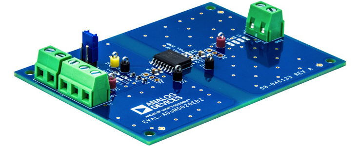 Compact and simple layout using ADuM5020
The small packaging (16-lead and 8-lead wide body SOIC) consumes very little PCB area, and no safety capacitance is required to meet the emissions targets. This makes the isolated power circuit smaller and less expensive than a discrete approach, such as an embedded stitching capacitor that requires four or more layers with customized spacing to produce the correct capacitance.
Meeting the Need for More Isolation Without More Complexity
The need for isolation is increasing with the growing electrification of automobiles and other vehicles. At the same time, heightened competition is driving the necessity for reducing costs and time to market. Coupled with these factors are more stringent regulatory requirements and the inherent complexity of isolation design. This confluence of market demands and challenges cannot be met successfully with conventional approaches to isolation. Fully integrated and safety-certified isolated dc-to-dc converters with documented EMC performance offer systems designers a better solution. They can dramatically reduce design complexity and ensure better EMC testing and compliance. With less time devoted to redesign, recharacterization, and retesting, designers can reduce board space, lessen risk, lower costs, and improve time to market.
Compact and simple layout using ADuM5020
The small packaging (16-lead and 8-lead wide body SOIC) consumes very little PCB area, and no safety capacitance is required to meet the emissions targets. This makes the isolated power circuit smaller and less expensive than a discrete approach, such as an embedded stitching capacitor that requires four or more layers with customized spacing to produce the correct capacitance.
Meeting the Need for More Isolation Without More Complexity
The need for isolation is increasing with the growing electrification of automobiles and other vehicles. At the same time, heightened competition is driving the necessity for reducing costs and time to market. Coupled with these factors are more stringent regulatory requirements and the inherent complexity of isolation design. This confluence of market demands and challenges cannot be met successfully with conventional approaches to isolation. Fully integrated and safety-certified isolated dc-to-dc converters with documented EMC performance offer systems designers a better solution. They can dramatically reduce design complexity and ensure better EMC testing and compliance. With less time devoted to redesign, recharacterization, and retesting, designers can reduce board space, lessen risk, lower costs, and improve time to market.
Author: David Carr is the applications engineering manager in the Interface and Isolation Group at © Analog Devices. He has spent much of his career involved in the definition, development, marketing, and applications support of high speed analog and mixed-signal products.
Existing discrete solutions, such as isolated flyback converters, have some benefits, including a low bill of material (BOM) cost, but there are drawbacks. A typical flyback design (Figure 1) contains a controller driving an isolation transformer, with rectification and filtering on the secondary, and an optically isolated feedback network. The error amplifier requires engineering effort to develop a compensation network to stabilize the voltage loop, and is dependent on optocoupler performance variability. Often seen as an inexpensive isolator for use in a power supply, an optocoupler has a variation in current transfer ratio (CTR) that will limit the voltage feedback performance and the effective operating temperature range. The CTR parameter is defined as the ratio of output transistor current to input LED current and is nonlinear, with substantial unit-to-unit variability. Optocouplers typically have a 2:1 uncertainty in initial CTR, which can degrade up to 50% after years of use in high temperature environments, such as those found in high power and high density power supplies. For a project manager, the discrete flyback approach seems better from a cost point of view, but there’s a trade-off in engineering effort and technical risk. Another concern with the discrete approach lies with meeting safety standards. Safety agencies scrutinize discrete design more closely, so achieving the necessary certifications for a discrete system design can often lead to multiple design iterations. Isolation in the system also adds complexity to the power design. A typical nonisolated design has the usual constraints, such as input and output voltage ranges, maximum load current, noise and ripple, transient performance, start-up characteristics, etc. By its very nature, the isolation barrier removes the ability to easily monitor input and output conditions simultaneously—making it more difficult to achieve the performance metrics. The separate ground domains also form a dipole antenna, and any common mode current that traverses the barrier will excite the dipole and lead to unwanted radiated energy. Passing the Tests Getting a discrete power design to pass EMC certification can take a few iterations to get right. EMC tests are lengthy and expensive, requiring teams to spend many hours preparing and monitoring the tests at an external EMC compliance facility. When problems do occur, it’s back to the lab to troubleshoot and make changes. Then the design must be completely recharacterized to ensure that the standard performance metrics weren’t compromised by the modifications. Then it’s back to the EMC facility for retesting. The final stage is getting the necessary safety certifications. This is another lengthy and expensive process, carried out by an external safety agency. A large amount of documentation must be prepared by the design team and is carefully examined by the agency. Anything new is given extra scrutiny, making reuse of previously certified circuits very desirable. A discrete isolated power design might need to be changed if the agency decides that it won’t meet the safety requirements. Once modified, the design would again need to be recharacterized and put through EMC testing. A Better Solution The answer to these problems is a fully integrated and safety-certified component with documented EMC performance. An example would be the ADuM5020/ADuM5028 low emission isolated dc-to-dc converters utilizing isoPower® technology. They provide up to 0.5 W of isolated power from a 5 V dc supply and operate from –40°C to 125°C. The products have been certified to multiple systems and component safety specifications by UL, CSA, and VDE. And they meet CISPR 22/EN 55022 Class-B radiated emissions requirements under full-load conditions on a simple 2-layer printed circuit board (PCB, Figure 2).Typical isolated flyback dc-to-dc converter.
Compact and simple layout using ADuM5020
The small packaging (16-lead and 8-lead wide body SOIC) consumes very little PCB area, and no safety capacitance is required to meet the emissions targets. This makes the isolated power circuit smaller and less expensive than a discrete approach, such as an embedded stitching capacitor that requires four or more layers with customized spacing to produce the correct capacitance.
Meeting the Need for More Isolation Without More Complexity
The need for isolation is increasing with the growing electrification of automobiles and other vehicles. At the same time, heightened competition is driving the necessity for reducing costs and time to market. Coupled with these factors are more stringent regulatory requirements and the inherent complexity of isolation design. This confluence of market demands and challenges cannot be met successfully with conventional approaches to isolation. Fully integrated and safety-certified isolated dc-to-dc converters with documented EMC performance offer systems designers a better solution. They can dramatically reduce design complexity and ensure better EMC testing and compliance. With less time devoted to redesign, recharacterization, and retesting, designers can reduce board space, lessen risk, lower costs, and improve time to market.
Author: David Carr is the applications engineering manager in the Interface and Isolation Group at © Analog Devices. He has spent much of his career involved in the definition, development, marketing, and applications support of high speed analog and mixed-signal products.