
© aydindurdu dreamstime.com
Application Notes |
Automotive Electronics market trends
The automotive market continues to be a focus end market for Linear Technology. This market has grown to approximately 20% of total sales in the last fiscal year, consistently growing faster than the overall growth of the company.
This is a product release announcement by Linear Technology Corporation. The issuer is solely responsible for its content.
The key growth drivers are the need for improved safety, fuel efficiency and advanced drivers assistance systems (ADAS). Furthermore, the proliferation of hybrid and all-electric vehicles continues to drive the need for innovative analog power conversion products. In addition to increased vehicle electronics, the world automotive market is also expected to grow steadily, thereby increasing demand for more vehicle production.
There are many applications in automotive electronic systems that require continuous power even when the car is parked, such as remote keyless entry, security and even personal infotainment systems, which usually incorporate navigation, GPS location and e-call functionality. It may be hard to understand why these systems must remain on, even when the vehicle is not moving, but the GPS aspect of these system needs to be “always-on” for emergency communications and security purposes (to pin point its location in the event of an accident, for example). This is also a necessary requirement so that rudimentary control can be employed by an external operator, if needed. Accordingly, a key requirement for these applications is low quiescent current from its electronic systems to extend battery life.
It is evident that the electronic content in vehicles will continue to grow no matter how many cars are sold each year. And the push for hybrid and all-electric vehicles is a contributing catalyst propelling the growth of this market. Along with the growing popularity of using batteries for power sources, there is also a demand for maximizing their useful lifetime. Battery imbalance, a mismatch in the state of charge of the individual cells that make up a pack, is a problem in large lithium battery packs, created by variations in the manufacturing process, operating conditions and battery aging. Imbalance can reduce a battery pack’s total capacity and potentially damage the battery pack. Imbalance prevents batteries from tracking from the charged state to the discharged state, and if not closely monitored, can cause batteries to be overcharged or over-discharged, which will permanently damage the cells.
The batteries used in either a hybrid/electric vehicle (HEV) or an electric vehicle (EV) battery pack are usually sorted by the battery manufacturer for capacity and internal resistance to reduce cell-to-cell variances in any given lot shipped to a customer. The vehicle battery packs are then built with carefully selected batteries to improve total cell-to-cell matching in the pack. This should theoretically prevent large amounts of imbalance from developing in the battery pack, but despite this, when building a large battery pack, both battery monitoring and battery balancing is required to maintain high battery capacity for the lifetime of the battery pack. It is here that Linear’s new battery management system (BMS) products have become well received and are currently one of the few BMS products road-proven in cars and busses in production.
Moreover, batteries are not just something for HEVs or EVs anymore, newly proposed automotive standard, LV148, combines a secondary 48V bus with the existing 12V system in automobiles in some 2017 models. The 48V rail includes an integrated starter generator (ISG) or belt start generator, a 48V lithium-ion battery and a bi-directional DC/DC converter for delivery of up to 10kW of available energy from the 48V and 12V batteries combined. This technology is targeted at conventional internal combustion automobiles, as well as hybrid electric and mild hybrid vehicles, as auto manufacturers strive to meet increasingly stringent CO2 emissions targets.
For this new standard, the 12V bus will continue to power the ignition, lighting, infotainment and audio systems. The 48V bus will supply active chassis systems, air conditioning compressors, adjustable suspensions, and electric superchargers/turbos and also support regenerative braking. The decision to use an additional 48V bus, which is expected be available across production model ranges soon, can also support starting the engine, which would make stop-start operation smoother. Moreover, the higher voltage means smaller cable cross-sections are needed, which reduce cable size and weight. Today's high-end vehicles can have more than 4 kilometers of wiring. Vehicles will become more like PCs, creating the potential for a host of plug-and-play devices. On average, commuters spend 9 percent of their day in an automobile. Thus, introducing multimedia and telematics into vehicles can potentially increase productivity, as well as providing additional entertainment.
The future for the 48V battery system is very much near-term. According to some auto manufacturers, a 48V based electrical system results in a 10%-15% gain in fuel economy for internal combustion engine vehicles, thereby reducing CO2 emissions.
Moreover, future vehicles that use a dual 48V/12V system will allow engineers to integrate electrical booster technology that operates independently of the engine load, thereby improving acceleration performance. Already in its advanced development phase, the compressor is placed between the induction system and intercooler and uses 48V to spin up the turbos.
Thus, it is clear that there is a need for a bi-directional step-down and step-up DC/DC converter that goes between the 12V and 48V batteries. This DC/DC converter can be used to charge either battery and allows both batteries to supply current to the same load if required. Most of the early 48V/12V dual battery DC/DC converter designs use different power components to step-up and step-down the voltage. As a result, Linear Technology designed and developed the LTC3871, a bi-directional DC/DC controller that uses the same external power components for the step-up conversion as it does for stepping down the voltage.
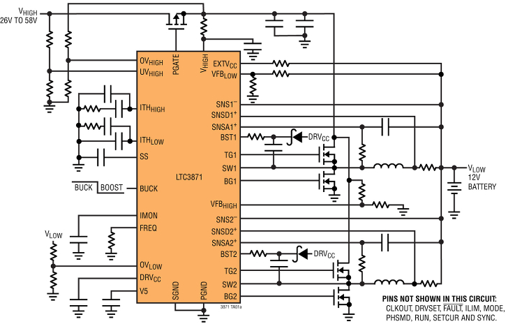
The LTC3871 is a 100V/30V bi-directional two phase synchronous buck or boost controller which provides bi-directional DC/DC control and battery charging between the 12V and 48V board nets. It operates in buck mode from the 48V bus to the 12V bus or in boost mode from 12V to 48V. Either mode is configured on demand via an applied control signal. Up to 12 phases can be paralleled and clocked out-of-phase to minimize input and output filtering requirements for high current applications (up to 250A). Its advanced current-mode architecture provides excellent current matching between phases when paralleled. Up to 3kW can be supplied in buck mode or in boost mode with a 12-phase design.
 When starting the car, or when additional power is required, the LTC3871 allows both batteries to supply energy simultaneously by converting energy from one board net to the other. Up to 97% efficiency can be achieved and the on-chip current programming loop regulates the maximum current that can be delivered to the load in either direction. Four control loops, two for current and two for voltage, enable control of voltage and current on either the 48V or 12V board nets.
The LTC3871 operates at a user-selectable fixed frequency between 60kHz and 475kHz, and can be synchronized to an external clock over the same range. The user can select from continuous operation or pulse skipping during light loads. Additional features include overload and short-circuit protection, independent loop compensation for buck and boost modes, EXTVcc for increased efficiency, ±1% output voltage regulation accuracy over temperature, along with undervoltage and overvoltage lockout. The LTC3871 has been qualified to meet AEC-Q100 specifications and was designed for diagnostic coverage in ISO-26262 Systems.
The LTC3871 is available in a thermally enhanced 48-lead LQFP package. Three temperature grades are available, with operation from –40°C to 125°C for the extended and industrial grades and a high temp automotive range of –40°C to 150°C. Figure 1 below shows its typical applications schematic. The P-channel MOSFET shown at the top of the schematic is for overcurrent and short-circuit protection.
-----
Author: Tony Armstrong, Director of Product Marketing Power Products; © Linear Technology Corporation
When starting the car, or when additional power is required, the LTC3871 allows both batteries to supply energy simultaneously by converting energy from one board net to the other. Up to 97% efficiency can be achieved and the on-chip current programming loop regulates the maximum current that can be delivered to the load in either direction. Four control loops, two for current and two for voltage, enable control of voltage and current on either the 48V or 12V board nets.
The LTC3871 operates at a user-selectable fixed frequency between 60kHz and 475kHz, and can be synchronized to an external clock over the same range. The user can select from continuous operation or pulse skipping during light loads. Additional features include overload and short-circuit protection, independent loop compensation for buck and boost modes, EXTVcc for increased efficiency, ±1% output voltage regulation accuracy over temperature, along with undervoltage and overvoltage lockout. The LTC3871 has been qualified to meet AEC-Q100 specifications and was designed for diagnostic coverage in ISO-26262 Systems.
The LTC3871 is available in a thermally enhanced 48-lead LQFP package. Three temperature grades are available, with operation from –40°C to 125°C for the extended and industrial grades and a high temp automotive range of –40°C to 150°C. Figure 1 below shows its typical applications schematic. The P-channel MOSFET shown at the top of the schematic is for overcurrent and short-circuit protection.
-----
Author: Tony Armstrong, Director of Product Marketing Power Products; © Linear Technology Corporation