
© Zettler
Components |
New Contact Configuration Design
As alternative energy technologies continue to grow globally, the PV inverter industry strives to minimize space, cost and power consumption.
The relatively expensive contactors in PV PCB relays need to be replaced with smaller and more energy and cost efficient devices requiring a radically innovative design approach to meet the high specifications from the industry and to meet official regulation criteria.
These relays require a double interruption for the AC side of PV inverters. In the past, it was only possible to produce inverters and relays capable of fulfilling isolation requirements at altitudes up to 2000 m above sea level, requiring contact spacing of at least 1.5 mm per contact. The then relevant standard, IEC 62109-1, stipulated a contact spacing of 1.8 mm at a system voltage of 1000 VDC, overvoltage category II, and for altitudes up to 2000 m.
Over time, these requirements became more and more stringent; the clearance and creepage distance requirements increased to 3000 m above sea level and a minimum of 2.05 mm per contact. A contact spacing of at least 2.32 mm would be needed for altitudes up to 4000 m (based on the altitude correction factor laid down in IEC standard 62109-1).
 Power SMD relay design concept
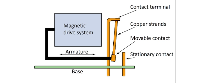
Clearly, new approaches had to be taken. Existing relays could not easily be modified structurally to achieve the increased contact spacing and handle the increasing current flows and associated demanding specifications. To conduct 200 A over printed circuit boards, the new design concept had to make it possible to attach the relays directly to copper rails screwed onto the PCB. Zettler Electronics developed the concept to mount a “Power SMD Relay“ with outwardly bent connections on the circuit board so that the screw connections and copper rails became a single entity.
This new contact system does not need the usual contact spring and requires practically no force to reset the contact spring, or even to move it in the first place. The contact spring comprises several extremely flexible copper strands that dangle on a “gallows“. No initial spring tension whatsoever is required - only the negligible friction and resilience forces of the copper strands have to be overcome to move the 200 A contact into its operating position, allowing peak reaction and holding power performance to be achieved.
With a holding power of only 0.6 W (also suitable for PWM), the AZSR1200 200 A relay for printed circuit boards has entered a new era, unimaginable just a few years ago. The additional advantage of this contact configuration is that the magnetic force that occurs with short circuit currents can be converted into the opposing force between parallel contact springs.
Avoiding welding risks
Contact welding risks that are often associated with short circuit currents in conventional contact spring solutions are now avoided. The magnetic force between parallel contacts springs, created by short circuit currents, usually pushes the contacts apart and causes them to open - frequently resulting in contact welding and relay damage.
With Zettler’s new contact system the stronger the power surge, the more the contacts are held together. Temporary short-circuit currents of up to 3000 A do not pose a risk for the relay contacts. When the fuse or circuit breaker that has been tripped is switched back on again, the relay is completely intact just as before the short circuit occurred. With Zettler’s AZSR1200 the contact spacing was increased to 4.6 mm, which means that the solar power plant of the future could even be operated in the Himalayas.
Preventing overheating through thermal bridge
An innovative engineering approach has been applied in the development of Zettler’s AZSR180, a single pole AC side 80 A solar relay. It features a thermally conductive copper bridge, riveted directly behind the contact studs of two movable parallel contacts. This ‘thermal bridge’ allows the two parallel contact springs to be thermally ‘connected’. In turn this provides an even distribution of excessive heat between the two contacts that can result from a significantly uneven distribution of currents carried in one vs. the other contact.
Even in the highly critical instance of a total failure of one of the two parallel-connected contacts, in which one would be completely isolated while the other would have to carry the entire current in a severe overload condition, the ‘thermal bridge’ will prevent extreme overheating of the latter contact and importantly, the inevitable destruction of the entire relay.
Innovative design approaches such as the new contact system or the thermal bridge ensure that the solar relays meet the high specifications from the industry as well as official regulation criteria. The solutions can be incorporated into a wide range of solar energy applications, enhancing the joining together of solar energy into power infrastructures.
-----
Autor: Alexander Stöckel, Productmanagement Electromechanical Components, © Zettler
Power SMD relay design concept
Clearly, new approaches had to be taken. Existing relays could not easily be modified structurally to achieve the increased contact spacing and handle the increasing current flows and associated demanding specifications. To conduct 200 A over printed circuit boards, the new design concept had to make it possible to attach the relays directly to copper rails screwed onto the PCB. Zettler Electronics developed the concept to mount a “Power SMD Relay“ with outwardly bent connections on the circuit board so that the screw connections and copper rails became a single entity.
This new contact system does not need the usual contact spring and requires practically no force to reset the contact spring, or even to move it in the first place. The contact spring comprises several extremely flexible copper strands that dangle on a “gallows“. No initial spring tension whatsoever is required - only the negligible friction and resilience forces of the copper strands have to be overcome to move the 200 A contact into its operating position, allowing peak reaction and holding power performance to be achieved.
With a holding power of only 0.6 W (also suitable for PWM), the AZSR1200 200 A relay for printed circuit boards has entered a new era, unimaginable just a few years ago. The additional advantage of this contact configuration is that the magnetic force that occurs with short circuit currents can be converted into the opposing force between parallel contact springs.
Avoiding welding risks
Contact welding risks that are often associated with short circuit currents in conventional contact spring solutions are now avoided. The magnetic force between parallel contacts springs, created by short circuit currents, usually pushes the contacts apart and causes them to open - frequently resulting in contact welding and relay damage.
With Zettler’s new contact system the stronger the power surge, the more the contacts are held together. Temporary short-circuit currents of up to 3000 A do not pose a risk for the relay contacts. When the fuse or circuit breaker that has been tripped is switched back on again, the relay is completely intact just as before the short circuit occurred. With Zettler’s AZSR1200 the contact spacing was increased to 4.6 mm, which means that the solar power plant of the future could even be operated in the Himalayas.
Preventing overheating through thermal bridge
An innovative engineering approach has been applied in the development of Zettler’s AZSR180, a single pole AC side 80 A solar relay. It features a thermally conductive copper bridge, riveted directly behind the contact studs of two movable parallel contacts. This ‘thermal bridge’ allows the two parallel contact springs to be thermally ‘connected’. In turn this provides an even distribution of excessive heat between the two contacts that can result from a significantly uneven distribution of currents carried in one vs. the other contact.
Even in the highly critical instance of a total failure of one of the two parallel-connected contacts, in which one would be completely isolated while the other would have to carry the entire current in a severe overload condition, the ‘thermal bridge’ will prevent extreme overheating of the latter contact and importantly, the inevitable destruction of the entire relay.
Innovative design approaches such as the new contact system or the thermal bridge ensure that the solar relays meet the high specifications from the industry as well as official regulation criteria. The solutions can be incorporated into a wide range of solar energy applications, enhancing the joining together of solar energy into power infrastructures.
-----
Autor: Alexander Stöckel, Productmanagement Electromechanical Components, © Zettler