

© juan-jose-tugores-gaspar-dreamstime.com
Application Notes |
Appendix C
Linear regulators are commonly employed to post-regulate switching regulator outputs. Benefits include improved stability, accuracy, transient response and lowered output impedance.
[chapter-index=Linear Technology AN101 link-to=24929, 24930, 24931, 24932, 24933]Please use the links below to navigate to the other part of this application note.[/chapter-index]APPENDIX C - Probing Technique for Sub-Millivolt, Wideband Signal Integrity
Obtaining reliable, wideband, sub-millivolt measurements requires attention to critical issues before measuring anything. A circuit board layout designed for low noise is essential. Consider current flow and interactions in power distribution, ground lines and planes.
Examine the effects of component choice and placement. Plan radiation management and disposition of load return currents. If the circuit is sound, the board layout proper and appropriate components used, then, and only then, may meaningful measurement proceed.
The most carefully prepared breadboard cannot fulfill its mission if signal connections introduce distortion. Connections to the circuit are crucial for accurate information extraction. Low level, wideband measurements demand care in routing signals to test instrumentation.
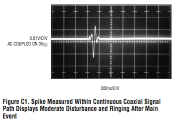
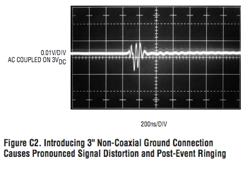
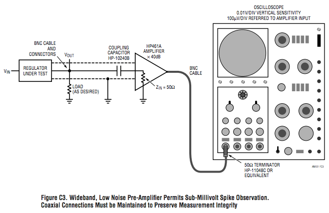
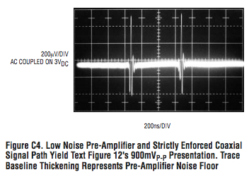
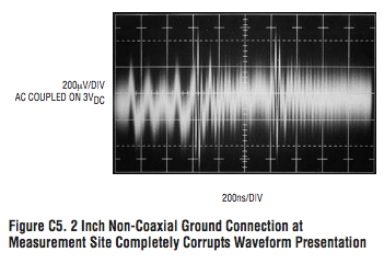
Issues to consider include ground loops between pieces of test equipment (including the power supply) connected to the breadboard and noise pickup due to excessive test lead or trace length. Minimize the number of connections to the circuit board and keep leads short. Wideband signals to or from the breadboard must be routed in a coaxial environment with attention to where the coaxial shields tie into the ground system. A strictly maintained coaxial environment is particularly critical for reliable measurements and is treated here1. Figure C1 shows a believable presentation of a typical switching regulator spike measured within a continuous coaxial signal path. The spike’s main body is reasonably well defined and disturbances after it are contained. Figure C2 depicts the same event with a 3 inch ground lead connecting the coaxial shield to the circuit board ground plane. Pronounced signal distortion and ringing occur. The photographs were taken at 0.01V/division sensitivity. More sensitive measurement requires proportionately more care. Figure C3 details use of a wideband 40dB gain pre-amplifier permitting text Figure 12’s 200µV/division measurement. Note the purely coaxial path, including the AC coupling capacitor, from the regulator, through the pre-amplifier and to the oscilloscope. The coaxial coupling capacitor’s shield is directly connected to the regulator board’s ground plane with the capacitor center conductor going to the regulator output. There are no non-coaxial measurement connections. Figure C4, repeating text Figure 12, shows a cleanly detailed rendition of the 900µV output spikes. In Figure C5 two inches of ground lead has been deliberately introduced at the measurement site, violating the coaxial regime. The result is complete corruption of the waveform presentation. As a final test to verify measurement integrity, it is useful to repeat Figure C4’s measurement with the signal path input (e.g., the coaxial coupling capacitor’s center conductor) grounded near the measurement point as in text Figure 13. Ideally, no signal should appear. Practically, some small residue, primarily due to common mode effects, is permissible.-----
-----
-----
-----
© Linear Technology