


© Zach Smith
PCB |
Super Simple SMT: Stencil8
Over the years, I’ve soldered a fair number of boards. I’ve also seen how professional factories produce their boards. This is my technique for doing it myself, and I hope it works as well for you as it does for me. :)
Note: the files needed to make the fixture, custom pcb setup, and stencil are on Github – Stencil8. This whole project is OSHW.
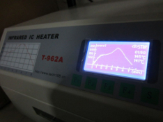
Required Tools Overview: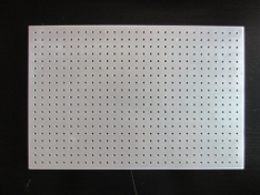
© Zach Smith
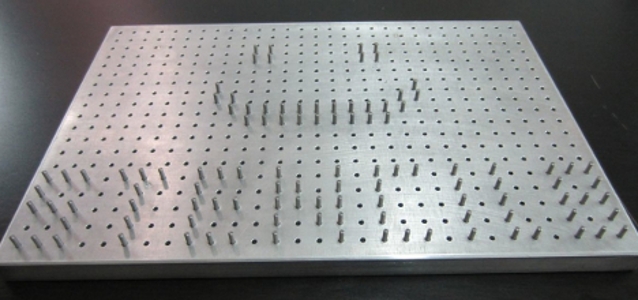
- PCB Fixture Block + Tooling Pins
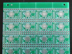
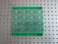
- PCB w/ Tooling Holes
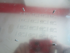
- Solder Paste Stencil
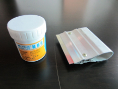
- Solder Paste + Squeegee
- Reflow Oven (or Hotplate)
- Isopropyl Alcohol (Rubbing alcohol.)
- Set your tooling pins onto the appropriate grid points.
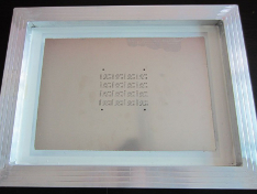
- Fit your PCB on the fixture.
- Place your solder stencil on the fixture.
- Use the Squeegee to apply solder paste to the stencil (and PCB).
- Gently remove the stencil from the figure.
- Use tweezers to place components on the appropriate pads.
- Reflow your PCB like normal using your reflow oven or hot plate.
- Solder your through-hole components (if any…)
- Test, test, test!
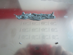
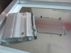
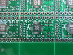
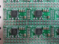
Step 1: Set your tooling pins The crux of this technique is using your precision tooling block + precision positioning pins to accurately align the PCB and the solder paste stencil. This helps you get very high quality solder paste deposition exactly where you want it. When you work with multiple boards, or when you work with very small parts it can be extremely difficult to align by hand. Setting the pins is easy. Put the pins in the right spot, and double check it using your PCB. Technically you only need 2, but I’ve found that 4 gives you a nice, snug fit that helps with preventing misalignment. Step 2: Fit your PCB on the fixture Your PCB should fit over the tooling pins and lay flat against the tooling block. If it doesn’t fit, try using 3 or 2 pins. Snug is good, but don’t force it. Step 3: Place your Solder Stencil on the tooling pins Using the same tooling pins, place your solder stencil onto the tooling block. Since the stencil is much bigger, it can be hard to get it aligned. I like to line up one hole first using light from above, then rotate the stencil around that pin until it slides over the rest of the pins. It should lay flat against the PCB when you are done. The pins should align the PCB and solder paste stencil very precisely. You should not see any green soldermask, only the silver pads where solder paste needs to be deposited. Step 4: Apply your solder paste Applying the solder paste is easy and fast. Place a dollop of solder paste onto the stencil. Use your squeegee to apply it across the face of the stencil. Angle the squeegee in the direction you’re moving it, and make sure to apply the paste both forwards and backwards to get every little nook and cranny filled. Apply a dollop: Squeegee it across: Step 5: Gently remove the stencil from the fixture Once you’ve applied the solder paste, carefully remove your stencil. You should immediately clean the stencil off with isopropyl (rubbing alcohol) so that you can use it again later. You should end up with beautifully applied solder paste like the picture above. I highly recommend leaving the PCB on the fixture. This will give you a stable base to work on, and will prevent you from knocking the PCB onto the floor or something like that. Step 6: Place SMT components using tweezers This is probably the trickiest part of the process. Use tweezers to pick and place each component onto the appropriate spot. A magnifying glass can help tremendously with this. Make sure you have good lighting and that you know what components go where. If you make a mistake you can dab a bit of solder on. Also, when the solder melts, it will self-correct to a small degree, so its okay if components are not exactly aligned. The boards in these pictures came out just fine, and you can see that the components are skewed a bit here and there. Step 7: Reflow your board like usual Use whatever process is convenient for you. I’m in love with this SMT oven here, but you may have your own preferred technique. If it works, go for it! Once the board has been soldered, it is a good idea to remove the flux using isopropyl alcohol and a toothbrush. Just don’t use it on your teeth afterwards! Step 8: Solder your through-hole components (if any) Using your trusty handheld soldering iron, solder in any through hole parts. If your board doesn’t have through hole parts, obviously skip this step. Step 9: Test, test test! Before using your board straightaway, test it! If you have a test fixture, then use that. If not, it is good to test for shorts between power/ground, as well as using a benchtop supply in current limiting mode set to a very low value and slowly ramp up the allowed current draw. If there is a short, this will allow you to catch it in a non-destructive way. You’re done! Using this technique you can solder very small parts that would otherwise be extremely difficult. I’ve successfully soldered 0402 components and QFN components with a 0.5mm pitch. You can easily do TQFP and any of the larger packages like 0603, 0805, and 1206. ----- More info can be found here.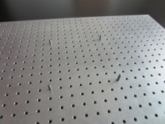
© Zach Smith