
© linear technology
Analysis |
How to resolve common I2C issues
I2C is a popular digital interface used for short-range chip-to-chip communication that features a simple 2-wire bus, ease of implementation, and up to 400kHz operation in fast mode.
Introduction
However, like any other standard, issues can arise when an application pushes the original I2C specification to its limit or simply when the specification falls short in addressing today’s system requirements. As systems become more complex, more I2C devices are added to the bus and may start to compromise certain parameters.
The most common issues I2C system designers face today are of electrical, timing or signaling nature. Increasing system size without exceeding the 400pF bus capacitance limit, compatibility with older non-compliant or unknown I2C devices, busses mysteriously stuck low, or simply not having enough device addresses available are all challenges I2C designers are fairly familiar with, but don’t always have easy answers to. This article discusses how Linear Technology’s I2C controllers resolve one or all of these issues simultaneously, so you can focus on designing your system, free of the I2C standard’s limitations and pitfalls.
Heavy Electrical Demands Met
The I2C standard specifies that the maximum bus capacitance cannot exceed 400pF. However, traces, long cables, and devices all possess and add capacitance to the bus, which makes it especially difficult for large systems to sometimes stay under the defined 400pF limit. Another common issue is I2C devices with different supply voltages can’t be mixed and matched on the same bus.
Some systems also require inserting and removing I/O boards from a live backplane, and without the proper precautions this can corrupt the backplane. Failure to address any of these electrical issues may compromise the I2C compliance, data integrity, or reliability of your system. Thankfully, I2C bus buffers have resolved these basic issues, providing busses with capacitive buffering, level shifting, and hot swapping capabilities by precharging the lines.
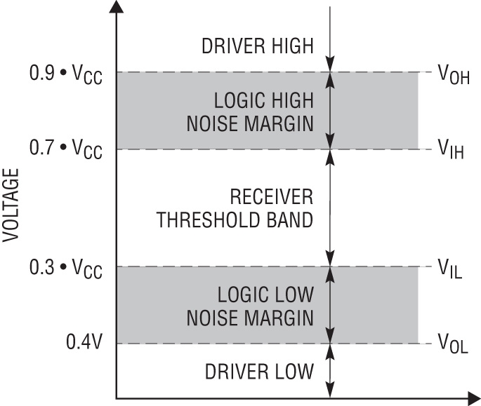
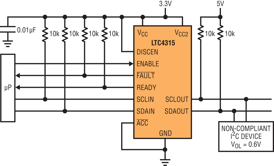
As systems continue to grow, new electrical issues arise and it has become more apparent that the benefits provided by earlier bus buffers have come at the expense of compromising certain I2C specifications. Bus buffers require a scheme to differentiate an externally driven logic low from their own driven low, which have resulted in buffers that either drive output logic lows (VOL) above the 0.4V II2C specification or buffers that drive a VOL with an offset. As more of these older buffers are added to the bus, logic low noise margin is compressed further, increasing the bus’ susceptibility to noise. Larger systems benefit greatly from a near- ideal bus buffer that restores logic-low noise margin to the I2C specification, namely, a fast buffer that is active until the bus voltages crosses the input logic-low (VIL) value of 0.3VCC and does not load the bus. An additional requirement in large systems is backward compatibility with buffer products whose rise time accelerators (RTAs) turn on below 0.3VCC or with products that drive a noncompliant VOL of 0.6V. Figure 2 shows Linear Technology’s LTC4315, a newer bus buffer that addresses all of the issues mentioned so far. The LTC4315 does the usual breaking of large bus capacitances into smaller <400pF segments, level translates bus supplies ranging from 1.4V to 5.5V, and provides hot swap capabilities so I/O cards can be safely inserted/removed from a backplane. Perhaps more importantly, the LTC4315 guarantees a high VIL of 0.3Vcc, ensuring a high logic-low noise margin at all times. As a result, multiple LTC4315s can be cascaded without worry of compressing noise margins, perfect for large or noisy systems. The LTC4315 is also interoperable with devices that drive a high VOL > 0.4V and with products whose RTAs turn on at voltages below 0.3VCC, so you can build a system without having to know or worry about what types of I2C will eventually connect to your system. Bad Timing Avoided There are two major timing issues that are prevalent in I2C systems. First, I2C signal rise times are generally dictated by the bus pull-up resistors, which are sometimes inadequate if a faster slewing bus is desired, such as the case in PICMG specifications which call for both the SCL and SDA signals to rise from 1V to 2.3V in 900ns with a 2.7kΩ pull-up to 3.3V and a 690pF load. Otherwise, high bus capacitance and limited pull-up current can critically lengthen rise times to the point of violating the max rise time I2C specification of 1µs at 100kHz or 300ns at 400kHz. Linear Technology offers many bus buffers with selectable rise time acceleration, like the LTC4315, as well as stand-alone dedicated rise time accelerators, like the LTC4311, which simply hang off the bus. These autonomous rise time accelerators provide strong, slew-limited, pull-up currents so that rise time requirements are met. The accelerators are automatically activated only during positive bus transitions and make the bus voltages rise at a particular rate, which improves both board and system reliability by providing smooth, controlled transitions during rising edges. Systems also become much less susceptible to noise on rising edges since the accelerator pull-ups present impedances significantly lower than bus pull-up resistances. Additionally, the accelerators permit the use of larger bus pull-ups, which reduce power consumption and improve logic low noise margin.Figure 1 -----
Figure 2 ----- All images have zoom function.
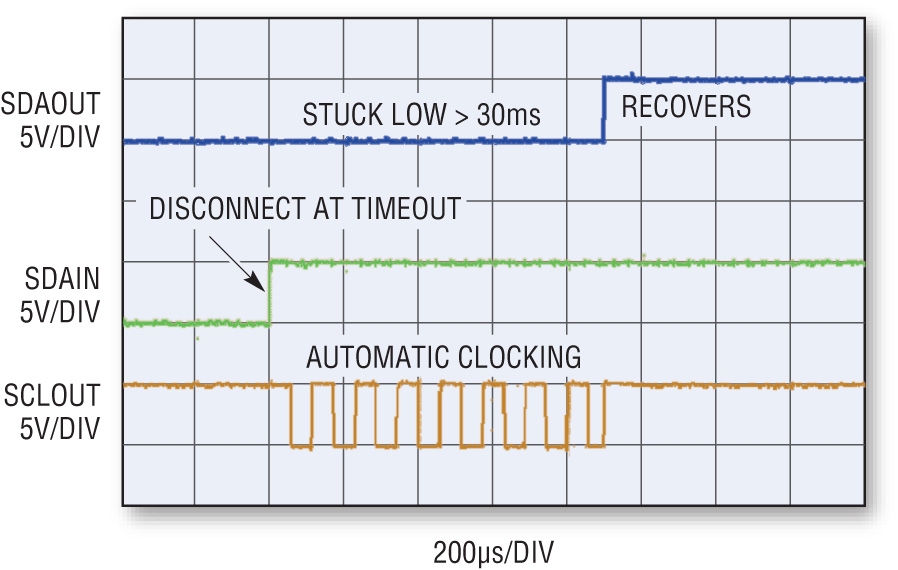
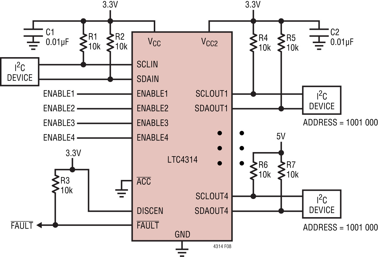
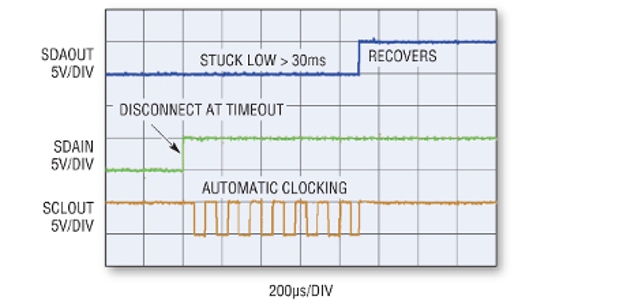
Another common timing issue is when the I2C bus sticks low – communication issues, data full of zeroes, and strange GUI behavior are all symptoms of a bus stuck low, where SCL or SDA can be stuck at ground usually due to faulty or confused I2C devices. If not corrected, a stuck device prevents other devices on the bus from communicating until the stuck device releases high. When a bus sticks low, the host must manually troubleshoot the bus, which usually results in a system reset that is disruptive, costly and time consuming. Stuck busses are easily resolved by using Linear Technology bus buffers with selectable stuck bus protection, like the LTC4315, where the SDA and SCL outputs are continuously monitored for a low state of more than 30ms. See Figure 3. If this occurs, the input-to-output connections for both I2C signals are broken, which prevents further communication with the stuck device, and the bus buffer generates up to 16 clock pulses on the SCLOUT pin in an attempt to free the card-side stuck bus. If the bus unsticks or if the 16 clock pulses are completed, a stop bit is generated to clear the bus for further communications and the input-to-output I2C connections are reconnected only when the bus is idle and not in the middle of an I2C transaction. Signaling Simplified The 111 physical addresses allotted by standard mode I2C may be sufficient for most systems, but larger systems may need to provide communication for more than 111 devices. Perhaps a more common issue is that system designers are forced to use slave devices that provide only a few unique addresses, necessitating the reuse of the same address (nested addressing). In these cases, Linear Technology I2C multiplexers should be used to permit the reuse of I2C physical addresses. Due to their bi-directional nature, these multiplexers can also be used to drive I2C data from the output buses to the input bus. Figure 4 shows the LTC4314 1:4 pin-selectable mux, where four I2C devices are all assigned the same address and individual enable pins allow users to choose which downstream busses the upstream bus will is be connected to. An LTC4306 1:4 software-selectable mux is also available and works in a similar fashion, but uses I2C commands instead of pins to choose which downstream busses the upstream bus will be connected to. These I2C multiplexers also integrate bus buffers, so all of the unique features Linear Technology bus buffers bring are also provided, including high noise margin, rise time acceleration and stuck bus protection. Conclusion At over 30yrs old, the I2C bus is still being widely used, where larger more complex systems continue to challenge its specifications and limitations. Designers can address a wide variety of common electrical, timing and signaling issues encountered during design, but a better practice would be to take preventative measures against these issues because you do not always know what types of I2C devices will ultimately connect to your system – a non-compliant I2C device or stuck bus may just be around the corner. By desiging in the the right combination of Linear Technology I2C bus buffers, rise time accelerators, and muxes from start, you can easily meet I2C specifications, while expanding your system without impractical restrictions and issues to slow you down. ----- Author: By Chris Gobok, Product Marketing Engineer, Mixed Signal Products, © Linear TechnologyFigure 3 -----
Figure 4 ----- All images have zoom function.